ISE Sit-Stand Скачать руководство пользователя страница 8

Tray adjustment is to be made after all technology has been installed.

Tray Leveling Adjustments (Left to Right)

STEP 1

Remove the trim cap at the back of the arm.

STEP 2

Use the 3/16” Allen Key to turn the top bolt at the  

back of the arm. Turn the bolt until the tray is level. 

STEP 3

Confirm that surface is level with spirit level. 

STEP 4

Replace the trim cap at the back of the arm.

+

+

+

+

LEVEL

ADJUST

3/16” 

Allen 

Key

ATTENTION:

Tray must be parallel to the work surface and swiveled 

90° to the base when adjusting. 

STEP 3

STEP 2

1. Adjust tension as necesssary 

2. Repeat on alternate side 

Light  

monitor

Heavy  

monitor

1

2

3

4

1

2

3

4

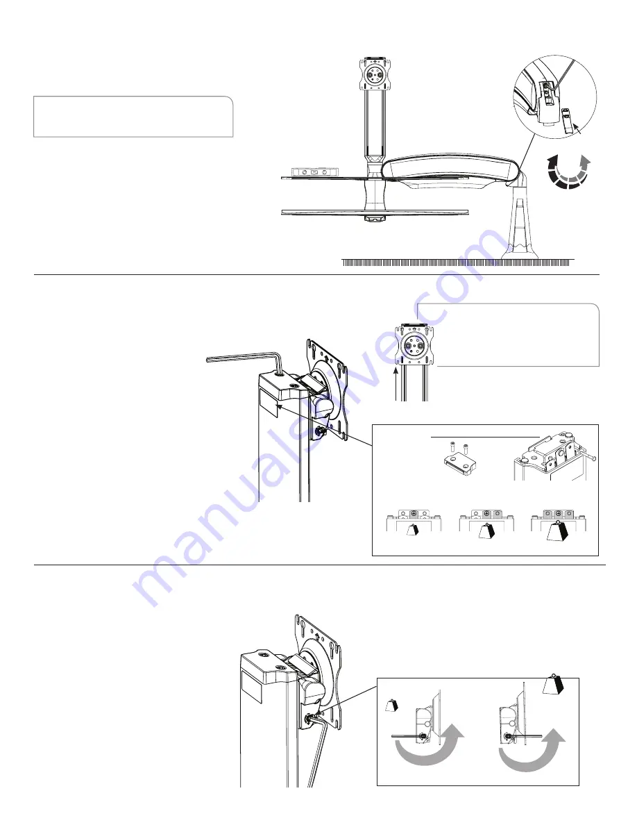
Tension Adjustment for the Monitor

Monitor Tilt Tension Adjustment

STEP 1

Use the 3/16” Allen Key to remove the two  

bolts securing the plastic top cap of the  

Float Tower. Remove cap.

STEP 2

Remove and install pins as necessary per the 

drawing while holding the monitor in the highest 

position. If pins are not needed, keep them inserted 

in the bracket hole for possible future use.

STEP 3

Once tension is acceptable, replace the cap and 

secure with the screws mentioned in STEP 1.  

Tighten with 3/16” Allen Key.

STEP 1

To adjust the monitor tilt tension, use a 3/16” 

Allen Key to adjust tension setting on the 

both sides of the VESA plate. Setting number 

1 is for the lightest monitor and 4 is for heavy 

monitors.  The factory default setting is 1.

STEP 2

Adjust the setting screw until a desirable 

tension is achieved.

STEP 1 & 2

STEP 4

1. Remove      

    top cap


3. Remove/install pins as necessary 

Light monitor

Medium monitor

Heavy monitor

TENSION ADJUSTMENT

ATTENTION:

Before adjusting the tension of the Float  

Tower, ensure that the monitor is the highest 

position on the Tower so that the spring tails 

are no longer in tension.

STEP 1 & 3

2. Hold monitor in the highest position.

8

Содержание Sit-Stand

Страница 1: ...INSTALLATION MANUAL FOR ACTIVATE SIT STAND WORKSTATION Maximum Load Single Monitor Arm 23 lbs Dual Monitor Arm 19 lbs Monitor Weight Single Monitor up to 20 lbs Dual Monitors up to 8 lbs each...

Страница 2: ...ER The manufacturer will bear no responsibility for any damages of any kind arising from improper installation of this product In no way will the manufacturer be held liable for any damage to the moni...

Страница 3: ...2 bolts into the bottom clamp Position the clamp plate KIT B Clamp Plate facing up over the tips of the bolts Tighten alternatively each bolt to 75 in lbs with the 7 32 Allen Key to firmly secure the...

Страница 4: ...gle bracket to the base Insert the grommet bolt through the washer KIT C Arm Bolt Washer Kit and upward facing clamp plate KIT B Clamp Plate From under the desk insert the grommet bolt assembly throug...

Страница 5: ...surface Hand thread each screw into the four holes in the worksurface the nuts have been pre mounted on the underside of the tray support arm and are held in place by the tape STEP 3 Remove the tape...

Страница 6: ...ing Quick Connect adapter mount the Quick Connect adapter Kit E VESA Mounting Plate Kit to back of the monitor with the M4 pan head screws provided Use a 2 Phillips screwdriver to secure screws Lift m...

Страница 7: ...le STEP 7 Adhesive cable clips are supplied and can be used to secure loose cables as required STEP 5 STEP 4 STEP 3 Lay all cables e g power VGA and mouse cables into the cable management tray STEP 4...

Страница 8: ...r Remove cap STEP 2 Remove and install pins as necessary per the drawing while holding the monitor in the highest position If pins are not needed keep them inserted in the bracket hole for possible fu...

Отзывы: