


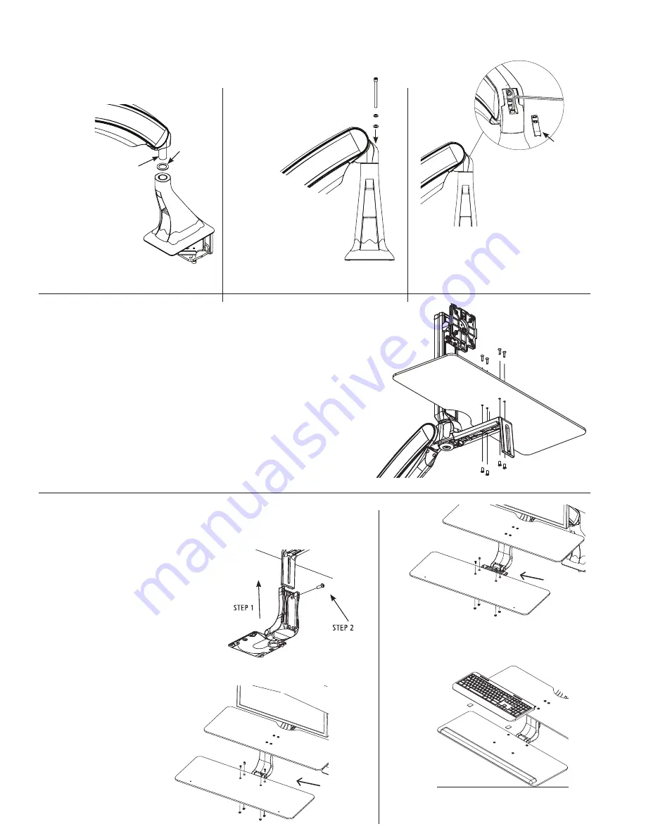
With the base already installed
Attaching the Arm to the Base
Installing the Work Surface
Installing the Keyboard Tray
STEP 1
Slide the large nylon washer
(
KIT C:
Arm Bolt/Washer Kit)
over the bottom pin of the
arm.
STEP 2
Set the main arm pin into
the base.
STEP 1
STEP 2
STEP 3
With arm in the lowest
position remove the plastic cap
at the back of the arm.
STEP 4
Keeping the arm in lowest
position, insert the bolt/
washer assembly (
KIT C:
Arm Bolt/Washer Kit) into
the back of the arm.
NOTE: Place nylon washer
on bolt first, followed by
metal washer
STEP 4
STEP 5
Keeping the arm down tighten
the bolt with the 7/32” Allen
Key until bolt is seated. Tighten
or loosen bolt to obtain desired
resistance for left to right arm
movement.
STEP 6
Replace the trim cap at the back of the arm.
STEP 5
STEP 6
STEP 1
Position the work surface on the tray support arm as shown. Do not remove the tape
from the underside of the tray support arm. Align the four holes in work surface with
the four front holes in the tray support arm.
STEP 2
Remove the four screws from the bag taped to the work surface. Hand thread each
screw into the four holes in the worksurface (the nuts have been pre-mounted on the
underside of the tray support arm and are held in place by the tape).
STEP 3
Remove the tape from the underside of the tray support arm. You can now tighten the
screws and nuts using the Philips screwdriver for the screws and the Slotted screwdriver
for the nuts.
STEP 1
Slide the keyboard tray head
into place as shown.
STEP 2
Adjust the keyboard tray head to the
desired height, and tighten into place
using the Tray Head Bolt (KIT D) and
3/16” Allen key.
STEP 4
Use two sided 3M Hook and Loop pads to secure keyboard to tray.
Position the keyboard tray on the tray head, align the four holes in
the keyboard tray to the tray head, and secure in place using the
screw pack taped to the keyboard tray. Note, insert plastic washer
onto screw first, followed by the metal washer and nut.
STEP 3
The keyboard tray can be mounted
to the tray head in two positions.
The front position will place the
keyboard tray (and the user’s
keyboard) closer to the monitor.
The back position will increase
the focal distance by placing the
keyboard tray further from the
monitor.
NOTE: Ensure
nylon bushing is
on the arm post
when inserting the
arm iinto the base.
5
Front Position
Back Position


