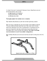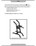
Appearance upon completion of Step 4.
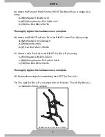
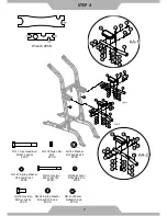
4A. Attach the Forearm Pad (P) to the RIGHT Dip Bar (I-R) as in image AA-2,
using:
2 - (56)
Washer D16xD8.4x1.6
2 - (57)
Spring Washer D12.3xD8.1x2.1
2 - (19)
Hex Bolt M8x1.25x70L
Thoroughly tighten the hardware once complete.
4B. Attach the RIGHT Dip Bar (I-R) to the RIGHT Lower Post (B) by using:
4 - (52)
Washer D13.5xD24x2.5
2 - (76)
Nylon Nut M12
2 - (7)
Hex Bolt M12x1.75x80L
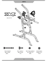
4C. Attach a Grip Post (H) to the RIGHT Dip Bar (I-R) by using:
1 - (51)
Washer D20xD10.5xT2.0
1 - (58)
Spring Washer D15.4xD10.2x2.6
1 - (18)
Hex Bolt M10x1.5x25L
Thoroughly tighten the hardware once complete.
4D. Repeat these steps for assembling the LEFT Dip Post (I-L).
Tip: The right Dip Bar (I-R) is marked with an R sticker. The left Dip Bar (I-L)
is marked with and L sticker
16
STEP
4
Содержание Power Tower
Страница 2: ......
Страница 8: ...6 ...
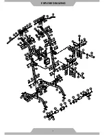
Страница 9: ...EXPLODE DRAWING 7 ...
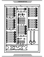
Страница 10: ...HARDWARE PACK 8 ...

