background image

l

Cool hue and warm hue for selection

l

32GB Build-in


memory

l

Support


photo


and


video


recording

l

Support APP connection via Wi-Fi

l

Built-in


digital


compass


and


motion


sensor

l

Replaceable Battery Pack

l

Convenient user interface

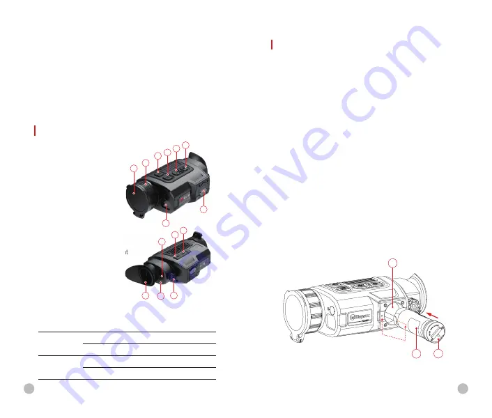
UNITS AND CONTROLS

1. Lens cap 
2. Lens focus ring
3. Power button
4. Menu button
5. Up/Ranging button
6. Down/Photo button
7.  Laser rangefinder
8. IBP-2 battery pack
9. Eyepiece
10. Infrared sensors switch
11. Eyepiece diopter adjustment
12. LED indicator
13. Type C port
14. HDMI port

LED indicator displaying the current status of the device

1

3 4

5 6

2

7

8

11

9

10

13

14

12

BATTERY AND SAFETY

Finder II series is supplied with a quickly removable 18650 Li-
ion battery pack, which enabled the device to be used for up 
to 5.5h. The battery should be fully charged before first use.

Battery Pack Installation

l

Turn up the puller 

(15)

 on the battery pack 

(8)

, and align the 

orange line 

(D)

 on the battery pack 

(8)

 with the triangle 

symbol 

(C)

 on the battery slot 

(16)

 and push the battery 

pack 

(8)

 into the battery slot 

(16)

.

l

When the battery pack is completely inserted into the 
battery slot, turn the puller 

(15)

 clockwise to lock the battery 

pack.

l

Close the puller 

(15)

, and the battery pack is completely 

installed.

l

Finder II series can only be powered by this battery pack. If 
other battery packs are used, it may cause irreparable loss, 
damage to the device, and can even possibly cause fire.

D

C

8

Battery Pack

16

Battery Slot

15

Puller

LED Color

LED Status

Operating

Mode

Normal

Fully charged

Flashing

Standby

Normal

Charging

Flashing

Less than 10% battery level

4

5

Содержание FINDER II FH35R

Страница 1: ...11th Guiyang Street YEDA Yantai 264006 P R China Tel 0086 400 998 3088 Web www infirayoutdoor com Email infirayoutdoor infiray com Operating Manual FL35R FH35R FL35R FH35R www infirayoutdoor com FINDER ǁ Thermal Imaging Monocular ...

Страница 2: ...l warning for Class 1M and 2M laser products This warning shall state that viewing the laser output with telescopic optical instruments for example telescopes and binoculars may pose an eye hazard and thus the user should not direct the beam into an area where such instruments are likely to be used ...

Страница 3: ...ideo recorder 3 PACKAGE CONTENTS l Finder II Thermal Monocular l Portable Bag l Type C USB cable l HDMI cable l Power adapter l IBP 2 battery pack 2 l IBC 2 battery charger l Hand strap l Neck strap l Cloth for cleaning optics l Operating manual DESCRIPTION The Finder II series are easy to carry and can be operated with one hand With its compact size and light weight it can be placed in the pocket...

Страница 4: ... battery pack which enabled the device to be used for up to 5 5h The battery should be fully charged before first use Battery Pack Installation l Turn up the puller 15 on the battery pack 8 and align the orange line D on the battery pack 8 with the triangle symbol C on the battery slot 16 and push the battery pack 8 into the battery slot 16 l When the battery pack is completely inserted into the ba...

Страница 5: ...V Power Adapter Socket Type C Port 17 19 20 USB Cable 18 15 B A A B 8 Battery Pack Method 1 Charging with Type C Port l Align the orange vertical line on the battery pack with the white triangle symbol next to the battery compartment on the Finder II and install the battery pack into the battery compartment of the product For details see Battery Pack Installation l Connect the Type C end of the da...

Страница 6: ...tery level is from 75 to 99 Battery is fully charged l It is not recommended to connect third party devices that consume more power than allowed l Do not disassemble or modify the battery pack without professional instructions Do not knock or drop the battery pack l The recommended operating temperature for the device is 20 C 50 C Do not use the device beyond this temperature range which may short...

Страница 7: ...on Switch cursor movement direction Save and exit calibration Up Ranging button Home screen state Turn on the laser ranging function Laser ranging mode Single ranging Switch ranging mode between single and continuous mode Shortcut menu 1 Adjust E zoom Adjust E zoom Shortcut menu 2 Adjust display brightness Adjust display brightness Main menu Navigation up Navigation up Defective pixels calibration...

Страница 8: ...e device Damage caused by failure to comply with the operating guidelines is not covered under warranty Power on and image adjustment l Remove the lens cap 1 Press and hold the Power 3 button for 2s to power on the device Then the home screen appears after 10s l Rotate the eyepiece diopter adjustment 11 to adjust the resolution of the icons on the display After the adjustment is completed for the ...

Страница 9: ... Battery level Blue 30 100 Yellow 20 30 Red Less than 10 Charging 15 Shut Down l After using the device press and hold the Power 3 button for 3 seconds The shutdown countdown screen will appear l When the countdown from 3 to 0 is completed as indicated by the countdown icon the device is powered off Then release the button The display is off the indicator is off and the device is shut down Standby...

Страница 10: ... and hold the Down Photo 6 button to start video recording l A tooltip showing the recording time showing in MM SS minutes seconds format will appear in the upper right corner of the display l The red dot in the tooltip flashes during recording l During recording short press the Down Photo 6 button to take a photo also l Stop the video recording by pressing and holding down the Down Photo 6 button ...

Страница 11: ...utton is required for ranging 239m l In the continuous ranging mode the distance of the target indicated by the cursor will be refreshed automatically every 1 second without any keystroke operation l The measurement range and accuracy is 800m 1m and it will be affected by fog and heavy rain and other weather l After the measurement is completed short press the Power 3 button to exit the laser rang...

Страница 12: ... quickly with a short press the Power 3 button 20 Composition and Description of the Main Menu Ultraclear Selection of the Ultraclear mode l Press and hold the Menu button 4 to enter the menu l Select the Ultraclear option l Short press Menu button 4 to turn the Ultra clear on off l When the Ultraclear mode is on the image contrast is enhanced which is suitable for rainy foggy and other harsh weat...

Страница 13: ...The icon is displayed on the status bar when it is on 22 Length Unit Selection of the length unit There are two units for selection meter M and yard Y l Press and hold the Menu button 4 to enter the menu l Select the Length Unit option l Briefly press the Menu button 4 to select M or Y More Get more settings l Press and hold the Menu button 4 to enter the menu l Select the More option l A short pre...

Страница 14: ...short press of the Menu button 4 switches the cursor direction from the 24 horizontal to the vertical and vice versa l The icon and text will be changed from white to blue when this direction is activated l Use the Up 5 Down 6 buttons to move the cursor to align its centre with the defective pixel With a short press to move 1 pixel and long press to move 10 pixels each time l After the cursor alig...

Страница 15: ...enu button 4 l Long press the Menu button 4 to exit to the upper interface Factory Reset Restore Factory Settings l Open the sub menu by pressing the Menu button 4 l Select the Factory Reset option l Enter the Factory Reset sub menu with a short press of the Menu button 4 l Select the option to reset to factory settings or to cancel with the Up 5 Down 6 buttons l Confirm your selection with a short...

Страница 16: ...s PIP FUNCTION PIP Picture in Picture function enables you to view a magnified digital zoom image in a separate window simultaneously with the main image l Press and hold the Menu 5 button to enter the menu l Select the PIP Mode option l A short press of the Menu 5 button switches the mode on off l A separate window appears at the top of the display simultaneously with the main image l The image in...

Страница 17: ...deposits l Check the condition of the rechargeable battery this should be charged and the electrical contracts there should be no presence of salts or oxidation 30 MAINTENANCE Maintenance should be carried out at least twice a year and consist of the following actions l Wipe the external surfaces of metal and plastic parts free of dust and dirt with a cotton cloth Silicone grease may be used for t...

Страница 18: ...at may cause interference To ensure stable Wi Fi operation relocate the device to an area with fewer Wi Fi networks or into an area with none Malfunction Possible reason Correction Wi Fi signal non existent or interrupted The device is outside the area of Wi Fi coverage There are obstacles between the device and the receiver e g concrete walls Relocate the device into direct line of sight of the W...

Страница 19: ...n damaged or the battery is defective send the device to our after sales service for repair Safety Instructions For The Power Supply Unit l Check the power supply unit cable and adapter for visible damage before use l Do not use any defective parts Defective components must be replaced l Do not use the power supply unit in wet or humid environments l Only use the original cable provided with the b...

Страница 20: ...onic devices He will provide you with further information Information on disposal in other countries outside of the European Union This symbol is only applicable in the European Union Please contact your local authority or dealer if you wish to dispose of this product and ask for a disposal option Intended Use The device is intended for displaying heat signatures during nature observation remote h...

Страница 21: ...sories used by this device should not contain any metallic components Body accessories that do not meet these requirements may not comply with RF exposure requirements and should be avoided Use only the supplied or an approved antenna FCC Statement FCC ID 2AYGT 26X Labeling Requirements This device complies with part 15 of the FCC Rules Operation is subject to the following two conditions 1 This d...

Страница 22: ...on This device was tested for typical body support operations To comply with RF exposure requirements a minimum separation distance of 0 5cm must be maintained between the user s body and the handset including the antenna Third party belt clips holsters and similar accessories used by this device should not contain any metallic components Body accessories that do not meet these requirements may no...

Отзывы: