background image

www.irrobot.com

14

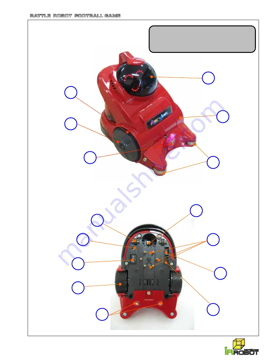
1.3.2  Parts Name of the Robot 

[MARUBOT(game robot)]

Head cover

Body part

Front

wheel

Ball guide

Magnetic

Ball Holder

Tire

Power 

Supplying 

Pins

Direction 

Control 

Tap

Program 

Download 

Port

Rear 

Wheels

Speed 

Control 

Switches

Front 

Wheels

Metal 

Balls

Power 

On/Off 
Switch

LED Light

6

5

4

15

14

13

12

11

10

9

8

7

3

2

1

• Size : 135 * 99 * 116 mm (W x D x H)
• Weight : 0.6kg
• Power : DC 12V

Содержание Marubot Football League 2 Players

Страница 1: ... players Instruction Manual Score Bar Version Important Please read the manual carefully before using this machine Keep this manual for your reference at anytime Specifications including design and color are subjected to change without notice ...

Страница 2: ...ne 44 9 2 Robot 46 9 3 Block Diagram 47 10 Customer Service 48 Precautions for use 2 1 Introduction 1 1 Product Information 7 1 2 Components 8 1 3 Product Specifications 9 1 3 1 Machine 9 1 3 2 Robot 14 2 Installation Instructions 2 1 General Instructions 17 2 2 Installations 17 2 3 Handling the robot 22 2 4 How to set the robot speed 23 3 How to play 24 4 Game Setting 4 1 Control Panel 26 4 2 Sou...

Страница 3: ... inspecting and maintaining the machines and troubleshooting must be assigned only to a qualified in shop maintenance person or industry specialist This booklet gives instructions that hazardous jobs in particular must be handled by an industry specialist Qualified in shop maintenance person and industry specialist are defined as follows Qualified in shop maintenance person A qualified in shop mai...

Страница 4: ...ign matter entering the inside of the machine Do not place objects near the ventilating holes Doing so could cause the internal temperature to rise excessively resulting in fire or equipment failure Do not bend the power cord by force or place heavy objects on it Doing so could result in electrical shock or fire Never plug or unplug the power cord with wet hands Doing so could result in electrical...

Страница 5: ...not plug or unplug the power cord with wet hands Doing so could result in electrical shock In handling the power cord follow the instructions below Otherwise fire or electrical shock may result If the power cord or power plug becomes damaged stop using the machine immediately and ask your nearest dealer to replace the parts Using a damaged power cord or power plug could result in fire or electrica...

Страница 6: ...indicated in this manual as well as settings and remodeling To clean the game machine wipe it with a soft cloth dampened in a neutral detergent Using thinner of other organic solvent or alcohol may decompose the material Electrical shock or equipment failure could be caused by water entering the inside of the machine WARNING Moving and transportation The game machine contains parts such as electro...

Страница 7: ...pplying method without any power cable or battery and Zigbee wireless communication control system Our techniques make it possible to operate the robot without any additional countermeasure to play the game once it is launched Please read this manual carefully before operating the machine to avoid any trouble from wrong use Thank you and enjoy with our robots Product design and specifications may ...

Страница 8: ...ing Automatic ball supplying function Stopper built in for fixing the machine position 4 wheels help easy movement to new location Specifications 1 Machine 1 Unit Dimension 1500 965 1790 W x D x H mm Weight 192 kg Main Power AC 220 230V 50 60Hz 110V Optional Working Electricity DC 12V DC 5V and AC 2 Robot 2 ea Dimension 135 99 116 W x D x H mm Weight 0 6 Kg Power supplied from the playground direc...

Страница 9: ...ts Hexagon socket screw key 2 5mm 1 Key 2 sets 1 for glass cover 1 for Main Body Manual Hand Cleaner 1 AC Power Cable 1 One set of spare parts for robot included Power supplying Pin Total 12 ea 2 robots each 6 pins Snap Ring for Wheel 2 Tires Magnetic Ball Holder screws Score Bar 1 ...

Страница 10: ...www irrobot com 9 1 3 Product Specifications 1 3 1 Machine Size 1500 965 1790 mm W x D x H Weight 192kg Power AC 110 220 230V 50 60 Hz ...

Страница 11: ... Wireless Robot Coin Selector 9 10 Robot Control part 2 1 11 Score FND Coin Collect box 8 Wheel Stoper 7 Start button 6 Credit Display 5 Time Display 4 Speaker 3 Turbo button 2 Robot Control part 1 1 Glass Cover 12 LED lamp 14 Ball Outlet 15 16 SCORE BAR ...

Страница 12: ...e start button Wheel Stopper 4 Wheels for movement and 4 stoppers for positioning Coin Collect Box Collects coins Wireless Robot Two robots Coin Selector Coin inserting hole Score FND Shows goal scores Glass Cover Glass cover of upper case Playground Controls robots on this playground Mainly power supplying from this board to the robots LED lamp Each LED lamp is located individually at 4 corner Ba...

Страница 13: ...w irrobot com 12 8 7 SMPS 4 Blow Up Pipe Control panel Multi outlet socket Air Blower 9 Main Board 6 10 Coin Box Assy Speaker 1 Score FND 2 LED Board 3 User Board 5 1 3 1 2 Inner Parts Name of the Machine ...

Страница 14: ...he playground Air Blower Discharges the ball to the playground with air User Board Controls joystick turbo button steering start button and time credit display SMPS Converts AC to DC Control Panel Controls all setting for playing games coin credit etc Multi outlet Socket Use for outlets need AC power directly Coin Box Ass y Coin selector and coin collect box positioned Speaker Speaker ...

Страница 15: ...ont wheel Ball guide Magnetic Ball Holder Tire Power Supplying Pins Direction Control Tap Program Download Port Rear Wheels Speed Control Switches Front Wheels Metal Balls Power On Off Switch LED Light 6 5 4 15 14 13 12 11 10 9 8 7 3 2 1 Size 135 99 116 mm W x D x H Weight 0 6kg Power DC 12V ...

Страница 16: ...ith different color of the LED light Power Supplying Pins Main power for the robots flows in through these pins from the power supplying board Program Download Port If there is any damage on the program it can be downloaded with this port Power On Off Switch Power On Off Switch Metal Balls Two metal balls help smooth movement of the robot Front Wheels Front Wheels Speed Control Switches Robot spee...

Страница 17: ...el Robot Main Board Motor Ass y Robot Body Left wheel Bottom Cover 1 2 3 8 9 10 4 5 6 7 11 12 Snap Ring for Wheel Rechargeable Battery Magnetic Ball Holder Ball Guide Screws Robot Power Board 1 3 2 1 Inner Parts Name of the Robot ...

Страница 18: ... rid of any wetness 6 Make sure to remove any dust and materials especially metallic articles on the power supplying board otherwise it is caused to short the power or create possible burning 2 2 Installations Installation or dismantling should be made by authorized expert Contact your local dealer if you have any trouble on installation Avoid any shock during transportation or installation Keep t...

Страница 19: ... Score Bar display assay with cable 1 Score Bar post with connection cable 1 Screw 1 4ea M4 x 10 Screw 2 2ea M4 2 x 13 Turn off the main power switch Connect the cable inside of score bar display assay to the cable in the post Assemble the score bar display assay and score bar post by using screw 1 Connect cables ...

Страница 20: ...n board and score bar post connection cable Connect cables Assemble the side panel and score bar post by using Screw 1 and attach the score bar post to the side body of the machine by using Screw 2 Screw 1 4ea M4 x 10 Screw 2 4ea M4 2 x 13 Assemble state ...

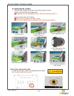
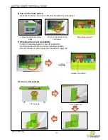
Страница 21: ...l down the cover Watch out you hand jammed Return the handle inside and close the locks Turn on the switch on the bottom of the robot Put the robots and ball in the playground Î Read page 20 2 3 Handling the robot first before put the robots in Then pull down the cover carefully Î Watch you hand when you make it close Î Check the playground is clean against any dusts and conductors 5 Connect a mai...

Страница 22: ...g the proper workability Insert coin and play game to check its workability Set the volume according to the surrounding condition Other functions of control panel are described on page 24 21 Open the front door using a key Turn on the switch on the control box Main Power switch Volume Controller Service Coin button Coin module Coin Collect box ...

Страница 23: ...n be worn away or changed its shape after long time operated Check its condition periodically and replace it If the wheel is cleaned out from time to time it will drive more smoothly 5 You have to check the power supplying pins periodically They are needed to replace immediately when they are run out Every 500plays are recommended The switch is Off The switch is On LED lamp is off LED lamp is on 6...

Страница 24: ... Dip Switch When setting is finished the power should be Off and On again 1 2 3 4 1 2 FASTER ON ON ON ON ON ON Moving Speed Control Turning Speed Control All dip switches are On position from the factory 1 2 ON OFF 1 2 OFF ON 1 2 OFF OFF 3 4 ON ON 3 4 ON OFF 3 4 OFF ON 3 4 OFF OFF NORMAL FAST FASTER SLOW SLOW NORMAL FAST ...

Страница 25: ...is 3 minutes Refer to P 26 27 3 Control the robot using joystick and steering Joystick control push up Move forward Pull down Move backward Steering control Turn left Turn to left Turn right Turn to right Turbo Button The robot will move faster in a moment when pushing the turbo button Only push turbo button The Robot will move forward faster at present location Push turbo button with Joystick con...

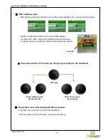
Страница 26: ... of goal will be shown on the score FND display The team who make a goal their robots will do goal ceremony The team who lose a goal their robots will show sad expression 6 The game is over after designated time is passed The game time is set as 3 minutes from the factory After the game is over both teams will do goal ceremony Score FND Start play When making a goal Wink and smile When loose a goa...

Страница 27: ... service push the service coin button The number of credit will be increased by 1 Mode Set Enter 4 4 Blow Button In case of the ball does not come out push the blow button 4 1 Control panel The Control panel is located inside of the door 4 Game Setting Open a lock with a key Sound Volume Service Coin Mode Set Enter Blow Refer to P 25 ...

Страница 28: ...utton for WINNER This mode is to set ticket numbers for a winner Push the Set button to increase ticket number up to 250 by 1 To initialize as 0 push the Mode button for DRAW This mode is to set ticket numbers for both players when they drew Push the Set button to increase ticket number up to 250 by 1 To initialize as 0 push the Mode button END If you push the Enter button it saves all menus you d...

Страница 29: ...r a game It can be adjusted from 30 to 570 seconds by 30 Set button Push 2 3 Sec shows Î Push Mode button 2 times shows Î Push Enter button and display shows Î Push Set button to put the number The number will be increased by 30 up to If you want to change the number or decrease it push Mode button and the display shows again and you can put new number again with Set button Î After setting the num...

Страница 30: ... not work Set button Push 2 3 Sec shows Î Push Mode button 9 times shows Î Push Enter button and display shows Î Push Set button to put the number The number will be increased by 30 up to If you want to change the number or decrease it push Mode button and the display shows again and you can put new number again with Set button Î After setting the number push Enter button and display shows Î Push ...

Страница 31: ... shows Tickets for Winner Push the Set button for 2 3 Seconds Display shows Î Push the Mode button 7 times Î The display shows Î Push the Enter button 1 time Î The display will be changed to or any number set before Î Push the Mode button Î The display will go back to Î Push the Set button until the display shown your desired number For example if you want to give 15 tickets to winner push the set...

Страница 32: ... that you want to use 3 Pull out the module slowly as shown 2 Setting Module Setting Up Photos No 1 4 6 Coin Selector Note The above coin selector shows only general type Therefore If you want to use your own coin then please discuss with your local dealer And also if you want to use bill selector or ticket dispenser additionally please discuss with your local dealer ...

Страница 33: ...ce a month If it is under dusty condition it may need once a week Clean the playground with dry towel Open two locks Turn the handle in the middle of the cover The handle comes out Grab the handle and pull up the cover Pull up until the shock up pull out fully Check the playground is clean Pull down the cover Watch out you hand jammed Return the handle inside and close the locks 5 2 Robots The rob...

Страница 34: ...he fuse in the Inlet socket 4 Check the light on the multi outlet If the light is off you need to replace the multi outlet C Above Light s using AC power are on but other parts are off In this case the most problems are on DC power and there may be conductors on the playground If so it make the short circuit and fix it as below Check the SMPS and if it does not work properly replace it If it works...

Страница 35: ... the control panel Try to play game whether it works properly If they are still not moving go to next step 6 2 2 One of two robots is not moving 1 Check the robot power switch is On in the bottom of the robot 2 Check the number of the power supplying pin under the robot It must be six 3 All of six have to have proper tension and tightly fixed 4 If the power supplying pin is missing broken or worn ...

Страница 36: ...ll move through the guide to the center pipe and Air Blow System will blow out the ball to the playground In case of free mode the ball is not come out automatically after the game over Both start buttons should be pushed to make the ball out The balls might be jammed at the entrance Ball guide pipe Push the blow button on the control panel 6 2 3 The Robot do not go straight 1 Check 6 power supply...

Страница 37: ...power switch and open the side door which control panel is positioned 3 Push set button on the control panel for 2 3 seconds will be shown in the display Push Mode button 12 times shows Push Enter button shows and both 11 scores will be shown on the score display as below 4 When replace new robot it needs to make new registration Turn the robot On and place the robot on the playfield Make sure tha...

Страница 38: ...avoid radio wave interference and it also needs to make team designation There are 2 dip switches on the user board One is 6 dip switches and the other is 4 dip switches 4 dip switches is for team setting team A and B by using No 1 dip switch This switch is On team will be B white robot 6 dip switches is for channel setting by using No 3 to 6 dip switches and choose one channel in the below Each r...

Страница 39: ... ON 14 CH OFF ON OFF OFF 15 CH OFF ON OFF ON 16 CH OFF ON ON OFF 17 CH OFF ON ON ON 18 CH ON OFF OFF OFF 19 CH ON OFF OFF ON 20 CH ON OFF ON OFF 21 CH ON OFF ON ON 22 CH ON ON OFF OFF 23 CH ON ON OFF ON 24 CH ON ON ON OFF 25 CH ON ON ON ON 26 CH List of robot channels is attached to the door that the control box is located ...

Страница 40: ...ondition Need to replace Power Supplying Pins condition 1 Separation of Power Supplying Pins It is easy to take out the pin by pulling it out If the pin doesn t pull out by hand use a long nose to take out At this point use cloth or tissue to cover the pin to protect then use a long nose to pull out 2 Power Supplying Pins Set Up Pushing in new pin with hand until it stops moving in Make sure that ...

Страница 41: ... irrobot com 40 8 1 2 Tires 1 Disentangle the snap ring with a snap ring pliers or a pinsette and disassemble the wheel 2 Remove the damaged tire on the wheel and set new tire A Snap ring Pliers A Pincette ...

Страница 42: ...mages 1 Use driver loosen the screw 2 Separate the ball guide Carefully 3 After separating the ball guide 4 Lift the Magnetic ball holder 5 Lifting the magnetic ball holder pull it out to the front 6 The shape after separating a magnetic ball holder from the robot Replace the Magnetic Ball Holder in reverse way ...

Страница 43: ...ic Cover with the hexagon socket screw key 2 5 2 Uncover the acrylic panel then you can find a compact fluorescent lamp 3 Turn a light bulb to the left 4 Separate a lamp from body Replace the lamp in reverse way You must power off the machine before replacement ...

Страница 44: ... s fixing the LED board 2 Replace the LED board in reverse way 8 2 2 LEDs in the each corner of the playground Disassemble order 8 2 3 Robot Control Parts Joystick Start button and Steering Notice You must power off the machine before replacement 1 Unscrew all bolts fixing the panel then uncover the part 2 Replace the part in reverse way ...

Страница 45: ...cerning this product please contact your local dealer IR ROBOT CO LTD Head Office 1302 2 401 dong Bucheon TechnoPark 193 Yakdae dong Wonmi gu Bucheon si Gyeonggi do 420 734 Korea Tel 82 32 326 3466 Fax 82 32 326 3468 E mail sales irrobot com Homepage www irrobot com ...

Страница 46: ...1 This device may not cause harmful interference and 2 This device must accept any interference received including interference that may cause undesired operation Do Not Any changes or modifications to the equipment not expressly approved by the party responsible for compliance could void user s authority to operate the equipment ...

Страница 47: ......

Отзывы: