IP-Link Installation Guide
6
Operator Interface
Connecting the IP-Link/CommLink II
Network
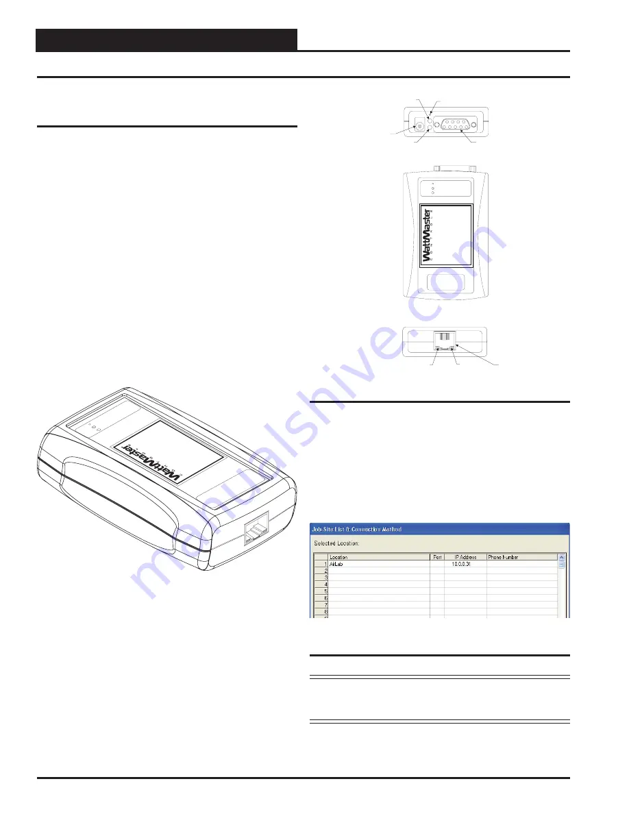
See Figure 8 for connection of the IP-Link to your control
system and for information on installing the IP-Link EPROM
in the CommLink II.
Connectivity
to a CommLink II through the network is
established when there is a route for TCP/IP traffi c generated
from a PC running Prism Software to communicate with the
IP-Link-enabled CommLink II. The CommLink II must have
the appropriate EPROM chip installed (SS0058) to initiate the
process of opening communications with the IP-Link and starting
the TCP port service.
Connecting the IP-Link to your network
or Internet
connection is accomplished by connecting an Ethernet RJ-
45 cable to the Ethernet port on the front of the IP-Link and
connecting the other end to your existing network’s hubs or
switches. Another confi guration may have the IP-Link connect
directly to the back of an ADSL or Cable Modem. In either
case, a link light should confi rm a positive Ethernet connection.
Connecting the IP-Link to a CommLink II
is accomplished
by connecting the serial cable with two DB9 connectors to the
back of the IP-Link and to the Remote Link or DTE port on the
back of the CommLink II. After powering up the two devices,
units will establish communication and there will be rapid and
continuous activity on the RLINK LED on the CommLink II.
This LED will blink non-stop and many times per second.
Connecting the Network
Prism Software Setup
is done by opening the
Job-Site List
& Connection Method Window
. Select an empty row and enter
a Site Name in the Location and an IP Address. Leave the Port
and Phone Number settings blank for that row. Select the Site
Location as you would normally and select Go Online from the
Communications Menu
.
Figure 7: Job-Site List and Connection List
NOTE:
These parameters serve only as an example of what
the confi guration could look like. Your IP address and
Location name could be different.
C
onnect
ne
iLAN-100
10/100BASE-T
LINK
ACT
SNET
POWER
MODE
PWR
SERIAL
Ethernet
Connection
RS-232 Serial Connector
Link LED
Serial NET LED
Power Connection
Use Included 120/9 Volt
Power Supply
Serial Power LED
Mode Select Button
ACT LED
Back View of IP-Link
Top View of IP-Link
Front View of IP- Link
IP-Link
OE415
www
.wattmaster
.com
10/100BASE-T
LINK
ACT
SNET
POWER
MODE
PWR
SERIAL
IP-Link
OE415
www
.wattmaster
.com
Figure 6: Back, Top, and Front Views of the IP-Link


