background image


Model : RS316-07 Hybrid EXP-

BP (COBRA) User’s Manual


PAGE    1    OF    23   


HYBRID BACKPLANE with EXPANDER   


User Manual


P/N : 2RAKVI007700 

Model

RS316-07 HYBRID EXP-BP(OCULINK) MODULE 


(BROADCOM COBRA BASED)


Version : A0


Содержание RS316-07

Страница 1: ...Model RS316 07 Hybrid EXP BP COBRA User s Manual PAGE 1 OF 23 HYBRID BACKPLANE with EXPANDER User Manual P N 2RAKVI007700 Model RS316 07 HYBRID EXP BP OCULINK MODULE BROADCOM COBRA BASED Version A0 ...

Страница 2: ...n Definitions 7 Connector Locations and LED Indicators 9 Connector Locations 9 LED Indicators 9 Hardware Specification 10 LED Behavior 11 Disk Bay LED 11 System Alarm 14 Smart Fan Control 15 Firmware Upgrade 17 Expander Chipset SAS3X36R Firmware Upgrade Description 17 Out Of Band through serial console 17 M058 Micro controller Firmware Upgrade Description 19 Management 22 Useful Console Commands 2...

Страница 3: ... Pin 5V and 2 piece of 2 4 Pin 12V power receptacles support up to 5V 40A 12V 60A current to satisfy the power needs of fully loaded HDDs 16 HDDs depends on backplane model The backplane implemented with smart fan control feature to support wide variety of fan modules by auto calibrating the installed fan modules at system boot This feature provides an efficient way to control the thermal heat exh...

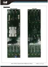
Страница 4: ...Model RS316 07 Hybrid EXP BP COBRA User s Manual PAGE 4 OF 23 Physical Outlook BOTTOM VIEW TOP VIEW ...

Страница 5: ...Model RS316 07 Hybrid EXP BP COBRA User s Manual PAGE 5 OF 23 Mechanical ...

Страница 6: ...e NVME1 NVME4 7 System_Fail LED JB1 2 Host facing interface SAS3 CN1 CN2 CN3 8 Mute_Button JB2 3 Firmware Programming Header JD1 9 Firmware Programming Header JC3 4 Main Power Connector PW1 2 PW3 4 10 I2C External Header JC1 JC2 5 FAN Connector FAN1 FAN4 11 Buzzer SUB1 6 M B Fan Speed Control JM1 12 SAS3x36R Expander chip U1 Connector Pin Definitions CN1 CN2 CN3 NVME1 NVME8 ...

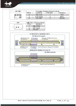
Страница 7: ... 2 12V 3 Tachometer 4 PWM Output JB1 SYS_ERR_LED Header PIN Definition 1 SYS_ERR_LED _ 2 SYS_ERR_LED _ JB2 MUTE_BUTTON Header PIN Definition 1 MUTE_BUTTON_ 2 MUTE_BUTTON_ JC1 JC2 I2C Header JM1 JM2 Function Description PIN Definition Communication BUS to Host Preserved 1 I2C_CLK 2 I2C_DAT 3 Ground JC3 Firmware Programming Connector PIN Definition PIN Definition 1 SDB_TX 2 1 8V 3 SDB_RX 4 Ground 5 ...

Страница 8: ... OF 23 JD1 JD2 Firmware Programming Connector PIN Definition PIN No Definition 2 ICE_CLK 1 VCC 4 ICE_DATA 3 Key 6 ICE_RST 5 Ground JM1 M B FSC 3 Pin Connector PIN Definition 1 MB_PWM 2 BP_TACH 3 Ground DISK1 5 9 13 DISK4 8 12 16 DISK2 3 6 7 DISK10 11 14 15 ...

Страница 9: ...2 16 3 DISK2 3 6 7 DISK10 11 14 15 SATA SAS Disk 2 3 6 7 SATA SAS Disk 10 11 14 15 LED Indicators No Location Description Location Description A DG1 DG4 DISK1 DISK4 Power LED LED1 4 DISK1 DISK4 Activity Failure LED B DG5 DG8 DISK5 DISK8 Power LED LED5 8 DISK5 DISK8 Activity Failure LED C DG9 DG12 DISK9 DISK12 Power LED LED9 12 DISK9 DISK12 Activity Failure LED D DG13 DG16 DISK13 DISK16 Power LED L...

Страница 10: ...onitor HDD bay inside temperature Buzzer SUB1 for Over temperature and FAN fail alerting High Speed Connector SFF 8621 OCULINK 42PIN Connector 8 NVME1 NVME8 SFF 8680 SAS29Pin Connector 8 for SATA SAS3 Disk SFF 8639 U 2 68Pin Connector 8 DISK1 5 9 13 DISK4 8 12 16 for SATA SAS3 Disk or NVMe SSD Power Signal Connector P4 2mm Disk Drive Power Connector 3 PW1 PW2 12V PW3 PW4 5V SYS_ERR_LED JB1 Turn on...

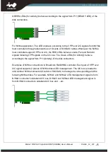
Страница 11: ...isk RAID rebuild and RAID consistent check There are 2 parts of LED Management on the backplane One is for SAS and another is for NVMe Please note that the disk slots can only accommodate SAS SATA or NVMe disk at a time since they share the same disk connector For SAS application The LEDs behave by following SGPIO signal coming through sideband bus inside the SFF 8643 cables Please refer to Sectio...

Страница 12: ... Rebuild signals following VPP signals on the I2C bus The Green LEDs for Activity behave according to the signal from P11 Activity of the disk connectors Examples of NVMe connections to Broadcom RAID HBA controller Each pair of VPP over I2C signal supports 2 pieces of NVMe disks LED management The I2C bus is leaded to odd number NVMe connector Oculink or SlimSAS to manage its corresponding and the...

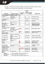
Страница 13: ...stence Blink_1 ActFlash 03 RQST CONS CHECK Rebuild Remap disk array Spare disk summoned for critical RAID rebuild Blink_1 ActFlash 03 RQST REBUILD REMAP Active Activity Off ActFlash 10 RQST ACTIVITY Warning Error In Critical Array Members in degraded RAID Off ActFlash 06 RQST IN CRIT ARRAY In Failed Array Members in broken RAID On ActFlash 07 RQST IN FAILED ARRAY Rebuild Remap Aborted R R Abort Sp...

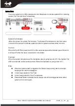
Страница 14: ...il When the Fan RPM is lower than 50 of the expected speed the indicator goes ON And it would go off when the issue is resolved or not existed Overheat When the system temperature at the backplane area is going beyond 45 C the System Fail LED is turned ON And would be turned off when temperature is going under 44 C Note When the system alarm is triggered the Buzzer beeps along with it and stops be...

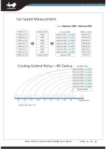
Страница 15: ...next reboot 2 Backplane starts fan calibration and calculates the corresponding PWM duty cycle for each level There are totally 8 speed levels to be sensed and used until next system boot 3 The 8 levels of fan speed are mapped to the temperature readings detected by thermistor spreading from 25 to 45 C in 3 75 degree C step 4 In normal operation when the system temperature changes to next level th...

Страница 16: ...Model RS316 07 Hybrid EXP BP COBRA User s Manual PAGE 16 OF 23 ...

Страница 17: ...e same time Ether one can be upgraded independently when required How to upgrade firmware 1 Out Of Band through serial console 2 In Band through SCSI Command Out Of Band through serial console IN WIN s SAS 3 12Gps Backplane implements a serial UART port allowing users to conduct firmware upgrade through it 1 Require a proprietary serial cable IN WIN made Please note that the connector to Backplane...

Страница 18: ...S316 07 Hybrid EXP BP COBRA User s Manual PAGE 18 OF 23 4 Configure serial port setting as 115200 N 8 1 5 Command fdl 0 0 y for system firmware upgrade in serial console Sending system firmware through Xmodem ...

Страница 19: ...mmand in serial console or power cycle to make new firmware take effect M058 Micro controller Firmware Upgrade Description The passive backplanes are planted Nuvoton M058 series MCUs for hosting disk LED indication Fan speed control and system fail alarm These MCUs are preprogrammed in manufacturing In most cases the MCUs are not required to reprogram unless there is issue needed to fix How to upg...

Страница 20: ... User s Manual PAGE 20 OF 23 1 Require Nuvoton ARM Cortex M0 programming tool Nu Me or Nu Link and install Nuvoton ICP Programming tool software 2 Connect Nu Link USB end to a host and the SWD end to Backplane ICE connector for each MCU ...

Страница 21: ...PAGE 21 OF 23 3 Make sure device is connected and select the binary file being programmed and then click on Start button to program firmware 4 Please refer to http www nuvoton com resource files NuLink_Adapter_User_Manual_EN_V1 01 pdf for more details ...

Страница 22: ...S Array Device info of CSE BRC bridge console only Configuration update fdl 1 0 y Download and Update MFG configuration feed it with MFG image file Firmware Update Fdl 0 0 y Download and update firmware Display info for all phys phyinfo help edfb power cable up PhyNum D no arguments displays default output help displays detailed help information edfb subcommand displays EDFB info power subcommand ...

Страница 23: ...Model RS316 07 Hybrid EXP BP COBRA User s Manual PAGE 23 OF 23 SAS address d also show virtural ports address Show POST info showpost Show MFG revision showmfg Show firmware revision rev ...

Отзывы: