38
| Optidrive Eco User Guide |
Version 3.06
www.invertekdrives.com
Par.
Parameter Name
Minimum
Maximum
Default
Units
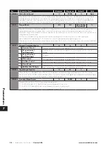
P1-10
Motor Rated Speed
0
30000
0
Rpm
This parameter can optionally be set to the rated (nameplate) Rpm of the motor. When set to the default value of zero, all speed
related parameters are displayed in Hz, and the slip compensation for the motor is disabled. Entering the value from the motor
nameplate enables the slip compensation function, and the Optidrive display will now show motor speed in estimated Rpm. All
speed related parameters, such as Minimum and Maximum Speed, Preset Speeds etc. will also be displayed in Rpm.
P1-11
Torque Boost
0.0
0.0
Drive Rating
Dependent
%
Torque Boost is used to increase the applied motor voltage and hence current at low output frequencies. This can improve low
speed and starting torque. Increasing the boost level will increase motor current at low speed, which may result in the motor
temperature rising - force ventilation of the motor may then be required. In general, the lower the motor power, the higher the boost
setting that may be safely used.
For IM motors, a suitable setting can usually be found by operating the motor under very low or no load conditions at
approximately 5Hz, and adjusting P1-11 until the motor current is approximately the magnetising current.
This parameter is also effective when using alternative motor types, P4-01 = 3, 4 or 5. In this case, the boost current level is defined
as 4 x P1-11 x P1-08.
P1-12
Primary Command Source
0
6
0
-
0
Terminal Control
The drive responds directly to signals applied to the control terminals.
1
Keypad control -
uni-directional
The drive can be controlled in the forward direction only using an external or remote
Keypad.
2
Keypad control -
uni-directional
As above.
3
PID Control
The output frequency is controlled by the internal PID controller.
4
Fieldbus Control
By the selected Fieldbus (Group 5 Parameters) – Excluded BACnet (see option 6).
5
Slave Mode
The drive acts as a Slave to a connected Optidrive operating in Master Mode.
6
BACNet MS/TP Mode
Drive communicates / responds as a slave within a BACnet network.
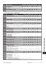
P1-13
Digital Input Function
0
14
1
-
Defines the function of the digital inputs. When set to 0 the inputs are user defined using group 9 parameters or the PLC software
function in the OptiTools Studio software package. When set to a value other than 0 the digital input configuration is defined by digital
input definition table (see section
8.1. Digital Input Configuration Parameter P1-13
).
P1-14
Extended Menu Access
0
30000
0
-
Parameter Access Control. The following settings are applicable:
P1-14 <> P2-40 and P1-14 <> P6-30: Allows access to Parameter Group 1 only.
P1-14 = P2-40 (101 default): Allows access to Parameter Groups 0 - 5 and group 8.
P1-14 = P6-30 (201 default): Allows access to Parameter Groups 0 - 9.
7
Parameters

