Mechanical installation
4
i
j
| BA 14.0196 | 05/2013
29
4.5.2
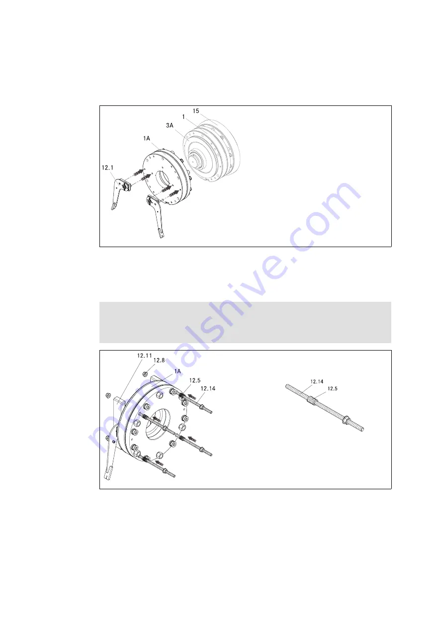
Assembly of the hand-release
BFL455-022-iso/d,s
Fig. 13 Applying the manual release lever
2. Mount the two complete levers (12.1) to the second complete stator (1A). For this
purpose, press the pins of the boards into the provided bore holes of the stator, use a
tool if necessary.
Note!
The boards are not symmetrical. The pin with the greater distance to the axis of
rotation must point to the outside. The levers also point to the outside.
BFK455-021.iso/dms
Fig. 14 Installation of the tension rods
3. Assemble four pre-assembled tension rods (12.14) with one spring (12.5) each
Carry out steps 4 and 5 separately for each side of every lever.
4. From the armature plate end, plug one pair of pre-assembled tension rods (12.14)
each into the provided bore holes (Ø11 mm) of the complete stator (1A). Insert the
springs (12.5) of the tension rod into the clearing hole of the armature plate (Ø16.5
mm) in the process.
Содержание BFK455
Страница 50: ...Notizen j BA 14 0196 05 2013 50...
Страница 51: ...Notizen i j BA 14 0196 05 2013 51...


