Assembly
18
They must always work in the same direction.
1.
Place the crosspieces through the loop openings in the pool liner
1
.
2.
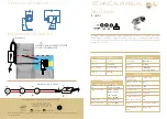
Attach the T-connector to the end of the crosspieces. Repeat this step until all
crosspieces are connected to each other.
The last connection may be difficult to complete. It is easier if you first lift the final
connector and the crosspiece by about 5 cm at the same time and then allow the
crosspiece to slide into the T-connector (see
Fig. F
, step 1).
Before you move on to assemble the uprights, ensure that the last connection is
fully inserted.
3.
Place the uprights into the belt loops in the middle of the pool liner.
4.
Insert the top of an upright into the T-connector (see
Fig. F
, step 2)
.
5.
Insert the bottom of the upright into an upright cap
5
.
6.
Repeat this process in the same direction until all the uprights are fitted.
7.
Once you have fitted the last upright, hold the crosspieces at various points and
shake the pool to ensure that all of the T-connectors, uprights and crosspieces are
firmly connected to one another.
8.
Ensure that all of the connecting pins are correctly in place and are pushed in.
9.
Pull the bottom of the uprights carefully outwards and align them all so that they
are exactly vertical and perpendicular to the subsurface.
10.
Attach the sticker with the safety symbols
38
to the side of the pool.
Setting up the pump
WARNING!
Risk of injury!
Setting up the pump incorrectly may result in injury.
− Read the safety instructions at the start of the user manual.
There are 3 fitting holes on the base of the pump. These holes are provided to allow
the pump to be fitted directly to the ground or a base plate in a perpendicular posi-
tion. The fitting holes are arranged in a triangle with a gap of 135 mm between them
and have a diameter of 7 mm.
The gap between the pump and the pool wall must be appropriate for the length of
the pump hoses
23
. When setting up, it must be ensured that the pump is accessible
for servicing and maintenance at all times.


