INSTALLATION & OPERATION MANUAL
DCC Pro
In-Vehicle DC-DC
Battery Charger
12VDC 25 AMPS
(VERSION R2.0)
Страница 1: ...INSTALLATION OPERATION MANUAL DCC Pro In Vehicle DC DC Battery Charger 12VDC 25 AMPS VERSION R2 0...
Страница 2: ...is based on quality performance and value and we are committed to product development in the DC power control and conversion field With roots in the commercial marine transport alternate energy and al...
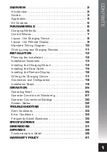
Страница 3: ...llation Essentials 13 Installing the Charging Device 14 Installing the Data Cable 15 Installing the Remote Display 16 Wiring the Charging Device 17 Connection and Configuration 18 Installation Steps 1...
Страница 4: ...ouble stacked printed circuit boards provide a compact footprint allowing for easy location and fixing in an engine bay All external components are designed to operate under high ambient humid conditi...
Страница 5: ...rging system and are all that is necessary aside from the external wiring to implement a fully operational charging and maintenance system for one auxiliary battery or bank batteries in parallel These...
Страница 6: ...tion and float stages it is in constant Voltage CV mode The DCC Pro is pre programmed with charging regimes for the following battery types which can be selected in the configuration set up process St...
Страница 7: ...he event you wish to add in a second charger for example it would not be necessary to purchase another display but simply order another Charging Device and Data Cable of the appropriate length The cod...
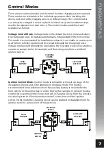
Страница 8: ...ost process and stepped down regulated in the buck process The main battery is the priority charging source if and when available This is because by comparison the vehicle s alternator can generally d...
Страница 9: ...disable the Charging Device Voltage mode would primarily be used where the Charging Device is located in a caravan or camper trailer for example and thus a long way from a switched ignition source Ign...
Страница 10: ...Battery Charging Device 12VDC 12VDC 25 Amps max COMMON NEGATIVE TERMINAL REMOTE DISPLAY OUTPUT IGNITION CONTROL TERMINAL MOUNTING FEET SOLAR PANEL POSITIVE TERMINAL MAIN BATTERY POSITIVE TERMINAL AUXI...
Страница 11: ...GHTNESS CONTROL CONFIRMATION SELECTION BUTTON ALSO USED TO TOGGLE BETWEEN DEFAULT AND ALTERNATE SCREEN FOR SWITCHING BETWEEN TWO CHARGING DEVICES ALSO USED AS BACK AND EXIT BUTTON Front View Back View...
Страница 12: ...5 Amps max IGNITION SWITCH SUPPLY FUSE 12V AUX FUSE 12V MAIN FUSE REMOTE DISPLAY CHARGING DEVICE DATA CABLE SOLAR PANEL OPTIONAL IGNITION SWITCH TO AUXILIARY EQUIPMENT TO ENGINE Standard Wiring Diagra...
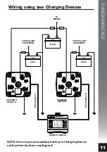
Страница 13: ...USE interVOLT Model DCC1225ACD Battery to Battery Charging Device 12VDC 12VDC 25 Amps max REMOTE DISPLAY CHARGING DEVICE B CHARGING DEVICE A TO AUXILIARY EQUIPMENT TO ENGINE TO AUXILIARY EQUIPMENT Wir...
Страница 14: ...cross over Crimp terminals are recommended over soldered lugs and should be terminated to automotive quality standards Incorrect or poor crimping is not only a mechanical issue wire separating from t...
Страница 15: ...y become loose thereby losing conductivity Manual reset circuit breakers are acceptable but check for de rating factor under elevated temperatures 3 Use good quality copper compression lugs for all te...
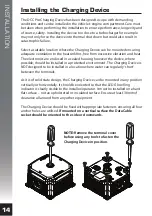
Страница 16: ...r the device where possible should be installed in a protected environment The Charging Device is NOT designed to be installed in a location where water can regularly short between the terminals As it...
Страница 17: ...ubber grommet is fitted to the cable and must be utilised to prevent damage to the cable sheath from any sharp metal edges The Data Cable is fitted with a PVC clamshell protector over the Remote Displ...
Страница 18: ...e to the surface details as follows Option A Screw Fixing This method utilises two suitable fasteners not supplied to attach the mounting base to the surface as per the diagram below Ball Joint Tensio...
Страница 19: ...against catastrophic failure It is mandatory however that inline fuses are fitted to protect the wiring in the event of an external short circuit The fuse rating should not be less than the continuous...
Страница 20: ...ition circuit The Remote Display is initially used for configuring the Charging Device upon installation Most importantly the Remote Display allows for selection of different battery types chemistries...
Страница 21: ...until it clicks into position To check the latch has engaged gently pull the connector it should not move If there is a need to remove the connector please see page 24 for instructions do not just pul...
Страница 22: ...rging Device end of the positive cable to the terminal marked MAIN using the special screw provided Connect the other end of the cable to the main battery positive Insert the fuse into the inline fuse...
Страница 23: ...enter the battery type selection menu II Use the and buttons to scroll and view the available options as outlined on page page 18 III Once the desired battery type is visible press the button to conf...
Страница 24: ...Configure the Charging Device Confirming configuration The next step is to confirm the ignition control setting Use the and buttons to select one of the two following options I Select NORMAL for conv...
Страница 25: ...ies the Charging Device will now enter stand by mode or a charging stage See pages 39 40 for more information As a result the LED indicators will reflect the current stage for example if the current s...
Страница 26: ...see operation section Connect a second Charging Device if available AB Using a pair of needle nose pliers apply a little pressure to the sides of the Data Cable plug and gently withdraw the plug assem...
Страница 27: ...evice as depicted below 1 2 3 The upper numeric display This is the top three digit numeric character set In conjunction with the icon this indicates the auxiliary battery Voltage to one decimal place...
Страница 28: ...r a detailed description of this function The Charging Device icons These indicate which battery Charging Device is currently being displayed when there are two Charging Devices in use Toggling the bu...
Страница 29: ...ctivated it will temporarily indicate the charging Voltage and power in Watts as described on page 29 If desired it can be activated to remain on by pressing and holding the button for 5 seconds until...
Страница 30: ...type on the multi function set see fig ii Toggle Between Two Charging Devices If two Charging Devices are installed and connected to a single display it is easy to toggle between both by momentarily...
Страница 31: ...er character set Auxiliary Charging Power This is displayed in Watts using the lower character set Charging Cycle Status This is indicated using the multi function character set and displayed as PV Ph...
Страница 32: ...y exit 2 Option 2 The audible alarm This option allows the operator to enable or disable the audible alarm which operates in conjunction with the warning system By default the audible alarm is enabled...
Страница 33: ...the button again and the word H i will appear above the text line SETTING iv Press again and the text SET HIGH will appear v Press or to increase or decrease the backlight brightness vi Press the butt...
Страница 34: ...ndicated by the LED Glow Ring with the advantage as the name indicates of being located away from the Charging Device These conditions are detailed in the table below Use the button to awaken the disp...
Страница 35: ...and displayed as CHECK DVC Internal fuses protect the Charging Device from catastrophic failure Please see Alert condition in the table below for further information Alert Displayed Possible Reason P...
Страница 36: ...ple a communications error is detected and the Remote Display will indicate COMM ERR See note 1 2 SYS 4 In the event there is a transmission issue during the configuration procedure and the Charging D...
Страница 37: ...operate in ignition or Voltage mode This primarily depends on where the Charging Device itself will be installed If it is located in the vehicle then ignition mode is recommended If it is located in...
Страница 38: ...s only IP40 not dust or water resistant Operating Temperature 20 C to 85 C Operating Humidity Up to 100 non condensing Charging Device Materials Heatsink Blue Plastics Black Plastics Transparent Plast...
Страница 39: ...DIMENSIONS 37 OK Length Width Height 60mm 36mm 59mm DCC Pro Remote Display Length Width Height 112mm 112mm 75mm DCC Pro Charging Device Footprint Mounting Centres 95mm x 95mm...
Страница 40: ...per termination etc by comparing the input Voltage at the main battery terminal with the Voltage at the Charging Device itself It does this by momentarily disconnecting the auxiliary battery thereby r...
Страница 41: ...lk charge is the stage when the Charging Device is operating in constant current mode In CC mode is producing the heavy current required to re charge a depleted battery as quickly as possible The boos...
Страница 42: ...CV stage is completed or terminated under the following conditions the programmed time cycle has finished pre determined by the battery type selected or the charge current is reduced below 4 Amps app...
Страница 43: ...expenses including diagnosis removal and or installation of the goods is the responsibility of the client including any freight costs The warranty shall be void where the goods have been used for a pu...
Страница 44: ...country of registration 2019 All rights reserved The entirecontents of this instruction manual shall remain the property of Amelec Australia Pty Ltd andshould not bereproduced without written permiss...