ZL2005PEV4
4
ZL2005PEV4DSr1.0
Quick Start Guide
Stand-alone Operation
1.
Set enable switch (EN) to “DISABLE”
2.
Apply load to VOUT+/VOUT-
3.
Connect power supply to VIN+/VIN-
(supply turned off)
4.
Turn power supply on
5.
Set enable switch (EN) to “ENABLE”
6.
Test ZL2005P operation
PMBus Operation
1.
Insert the Zilker Labs Eval Software CD
2.
Install the Eval Software by running
setup.exe from the ZL_Eval_Installer folder
on the CD.
3.
Connect a USB/SMBus adaptor (J2) to the
EVB (J10)
4.
Select a SMBus address with the jumper on
J12
5.
Connect supplied USB cable from computer
to EVB
a.
Upon first time connection, the Found
New Hardware Wizard will appear.
Select “No, Not this time” and click
Next
b.
Select “Install from a list or specific
location (Advanced)” and click Next
c.
Select “Search the best driver in these
locations” and only select the “Search
removable media” option, then click
Next
d.
If you encounter a popup warning during
driver installation, click the “Continue
Anyway” button
6.
Follow steps 1 - 4 under Stand-alone
Operation
7.
Invoke “Zilker_Labs_Eval” from the Start
menu under Zilker Labs
8.
Monitor and configure EVB using the
informative pages in the evaluation software
9.
Test the ZL2005P operation
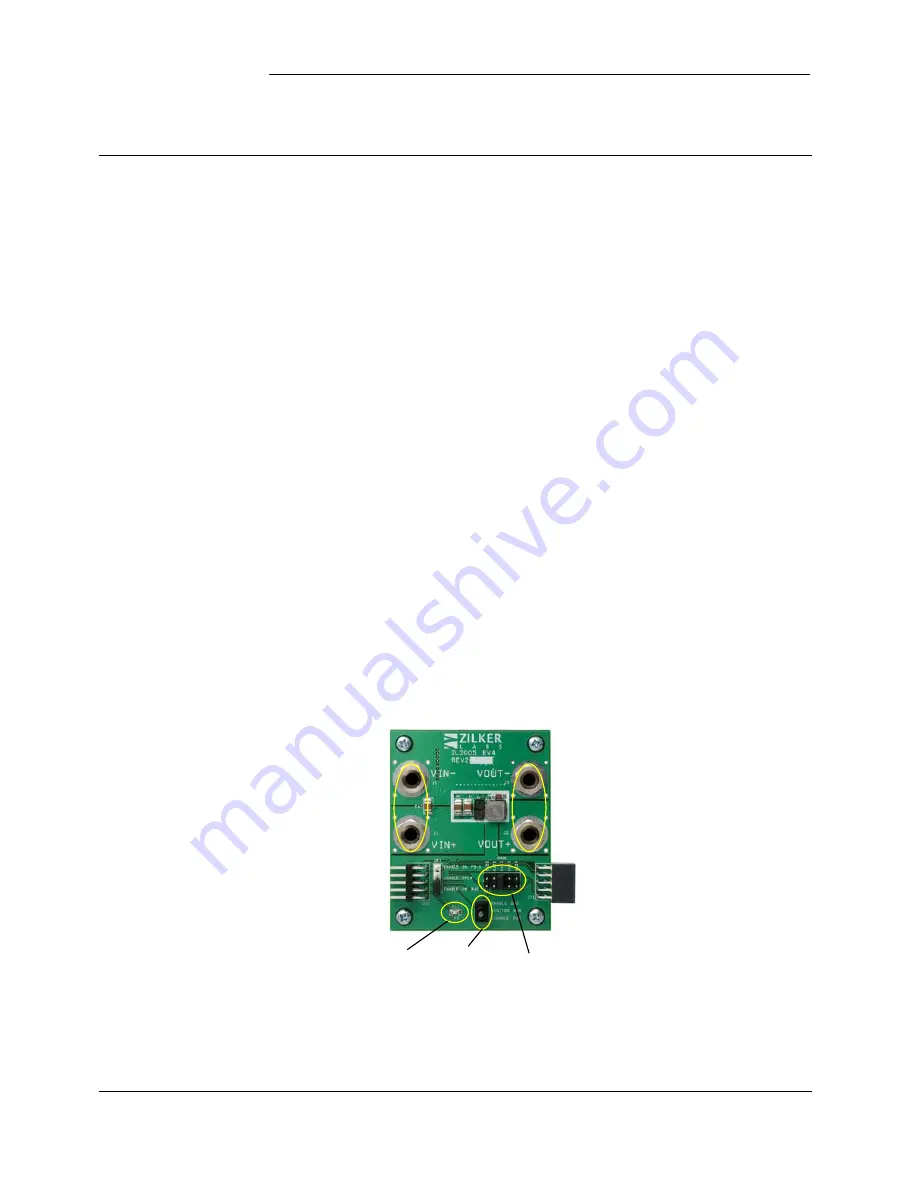
Figure 2. ZL2005PEV4 Evaluation Board
Connect input
voltage here
Connect load
here
Connect SMBus
controller here
Connect other
eval boards here
PG LED
EN Switch
Address select
Содержание ZL2005P
Страница 7: ...ZL2005PEV4 ZL2005PEV4DSr1 0 7 Board Layout Figure 5 PCB Silk Screen Top ...
Страница 8: ...ZL2005PEV4 8 ZL2005PEV4DSr1 0 Figure 6 PCB Top Layer ...
Страница 9: ...ZL2005PEV4 ZL2005PEV4DSr1 0 9 Figure 7 PCB Inner Layer 1 ...
Страница 10: ...ZL2005PEV4 10 ZL2005PEV4DSr1 0 Figure 8 PCB Inner Layer 2 ...
Страница 11: ...ZL2005PEV4 ZL2005PEV4DSr1 0 11 Figure 9 PCB Bottom Layer Top view ...
Страница 12: ...ZL2005PEV4 12 ZL2005PEV4DSr1 0 Figure 10 PCB Silk Screen Bottom Top View reversed ...


