Application Note 1829
3
AN1829.0
March 14, 2013
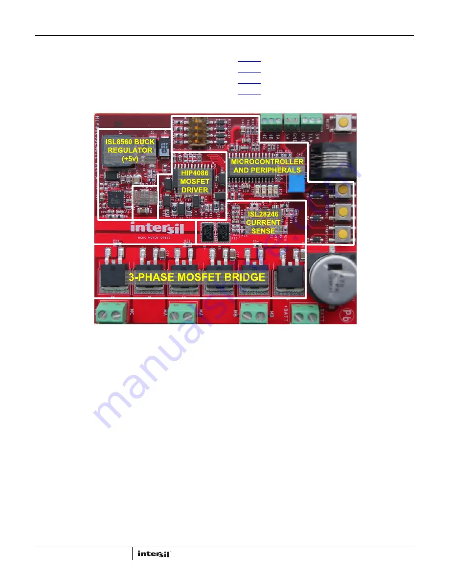
3-phase Bridge
The 3-phase bridge is composed of six F540NS power MOSFETS
(100V, 33A). Each FET is driven by one of the six driver outputs of
the HIP4086. Dead time is provided by the controller (optionally,
dead time can be provided by the HIP4086).
Related Literature
•
FN4220
HIP4086, 80V, 500mA, 3-Phase MOSFET Driver
•
FN6555
ISL6719, 100V Linear Bias Supply
•
FN9244
ISL8560, DC/DC Power Switching Regulator
•
FN6321
ISL28246, 5MHz, Single and Dual Rail-to-Rail
Input-Output (RRIO) Op Amps
Setup and Operating Instructions
Required and Recommended Lab Equipment
Lab supply (or battery), 15V minimum to 60V absolute
maximum. The current rating of the lab supply must have
sufficient capacity for the motor being tested. If a battery is the
power source, it is highly recommended that an appropriate fuse
be used listed as follows:
• Bench fan
• Test motor
• Multichannel oscilloscope, 100 MHz
• Multimeter
• Temperature probe (optional)
CAUTION: If the HIP4086DEMO1Z is used for an extended period
at high power levels, it may be necessary that a fan be used to
keep the temperature of the bridge FETs to less than +85°C (as
measured on the heat sink plane).
1. Connect the 3-phase motor leads to the MA, MB, and MC
terminal blocks. For high current applications, it is
recommended that both terminals of each block be used. It is
also recommended that during initial setup the motor
not
be
mechanically loaded.
2. Connect the HALL sensor leads of the motor to the HA, HB,
and HC terminals. The +5V bias and ground leads must all be
connected.
3. Rotate the R13 potentiometer to the left (CCW) until it clicks.
This will set the starting voltage on the motor to a minimum.
4. Setup the dip switch for the correct switching sequence (see
the switching sequence tables at the end of this application
note).
5. With a lab supply turned off but previously set to the desired
bridge voltage, connect the lab supply (or battery) to the
+BATT and -BATT terminal block.
6. Ensure that the motor is securely mounted prior to proceeding
with the following steps. Also, do not exceed the maximum
rated RPM of your motor.
7. Turn on the lab supply. Observe that the four LEDS turn on and
off, one after another. This initial flash of the LEDs indicates
that power has been applied. After the initial flash, all LEDs
will be off. Operation of the motor is now possible. Note that
the dip switch options are read at initial turn-on and changing
the settings after power is applied will have no effect. As an
ISL6719
(+12v)
FIGURE 3. MAJOR CIRCUIT LOCATIONS
Содержание HIP4086
Страница 20: ...Application Note 1829 20 AN1829 0 March 14 2013 FIGURE 21 TOP LAYER REV A PCB Layout Continued ...
Страница 21: ...Application Note 1829 21 AN1829 0 March 14 2013 FIGURE 22 LAYER 2 REV A PCB Layout Continued ...
Страница 22: ...Application Note 1829 22 AN1829 0 March 14 2013 FIGURE 23 LAYER 3 REV A PCB Layout Continued ...
Страница 23: ...Application Note 1829 23 AN1829 0 March 14 2013 FIGURE 24 BOTTOM LAYER REV A PCB Layout Continued ...


