


IS-1500 User Guide
Thales Visionix, Inc.
MNL- 0024 (D)
Page 17 of 59
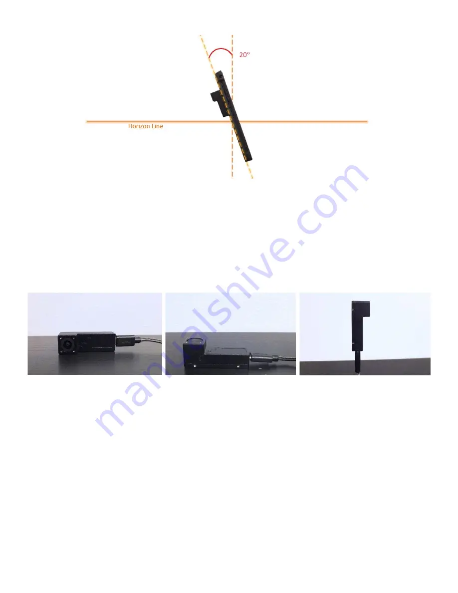
Figure 9 – Optimal 20° Pitch
The VINS algorithm maintains an extended Kalman filter (EKF) to enable bias correction and a certain level of movement prediction.
The EKF is state based, meaning that it is updated with each new tracking calculation. This also means that when tracking is first
initialized, the filter does not have much data and can be less reliable. To ensure the EKF receives more reliable data upon
initialization, keep the tracker still while tracking is initializing (before data begins streaming from sfHub).
To help optimize tracking performance, it is good practice to begin tracking by exercising the InertiaCam’s NavChip. To do this, begin
by placing the InertiaCam on a level surface with the camera facing up. Proceed to rotate the InertiaCam about 90° in each axis, leaving
it still for five seconds or more between each rotation. Be sure not to obstruct the camera during this process. Exercising the IMU
allows the EKF to begin accumulating IMU bias data and apply accurate corrections to the raw data.
Figure 10 – Exercising an IMU
If optical information in the VINS filter is determined to be unreliable due to a particularly high error estimates in the EKF, data
from the IMU will carry more weight in the tracking calculations. For instance, when the InertiaCam is rotated very quickly, or if its
vision is temporarily obstructed, VINS tracking will discard all of the features it had previously identified and will need to characterize
a completely new set of features. Because the system doesn’t have known distances for these features yet, the quality of the tracking
data may slightly and temporarily decrease. However, the EKF data will allow the system to rely more heavily on IMU data while the
new VINS features are established. This allows the system to stay relatively stable and continue tracking accurately under these
conditions.
If the InertiaCam’s vision is obstructed for long periods of time, the system will begin to rely almost entirely on the IMU data from
the NavChip. As discussed earlier, when the IMU is used exclusively to provide position, there is a high rate of drift. As an example,
after connecting to the InertiaCam and beginning tracking, the camera of the InertiaCam is covered. Soon after this, the tracker’s
position can be seen drifting away at an increasingly rapid rate. This behavior is known as a divergence. The software is designed to
recognize this divergence and counter it by resetting the filter and returning the tracker position back to the origin. Figure 11 shows
the 3D Data Display of a divergence that has resulted in a filter reset.