background image

Connecting the Adapter to an MVIP Bus

16

Interphase Corporation

How to Configure MVIP Electrical Termination
on the 

i

SPAN

-PRI

The factory default configuration for the 

i

SPAN

-PRI adapter 

does not require jumpers. 

If the adapter does not have to be electrically terminated, do 
not insert any jumpers into the 2-pin connectors. 

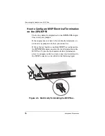
If this is the last board in a multiple MVIP bus configuration, 
the 

i

SPAN

-PRI adapter requires electrical termination in the 

MVIP bus. To provide the required electrical termination, 
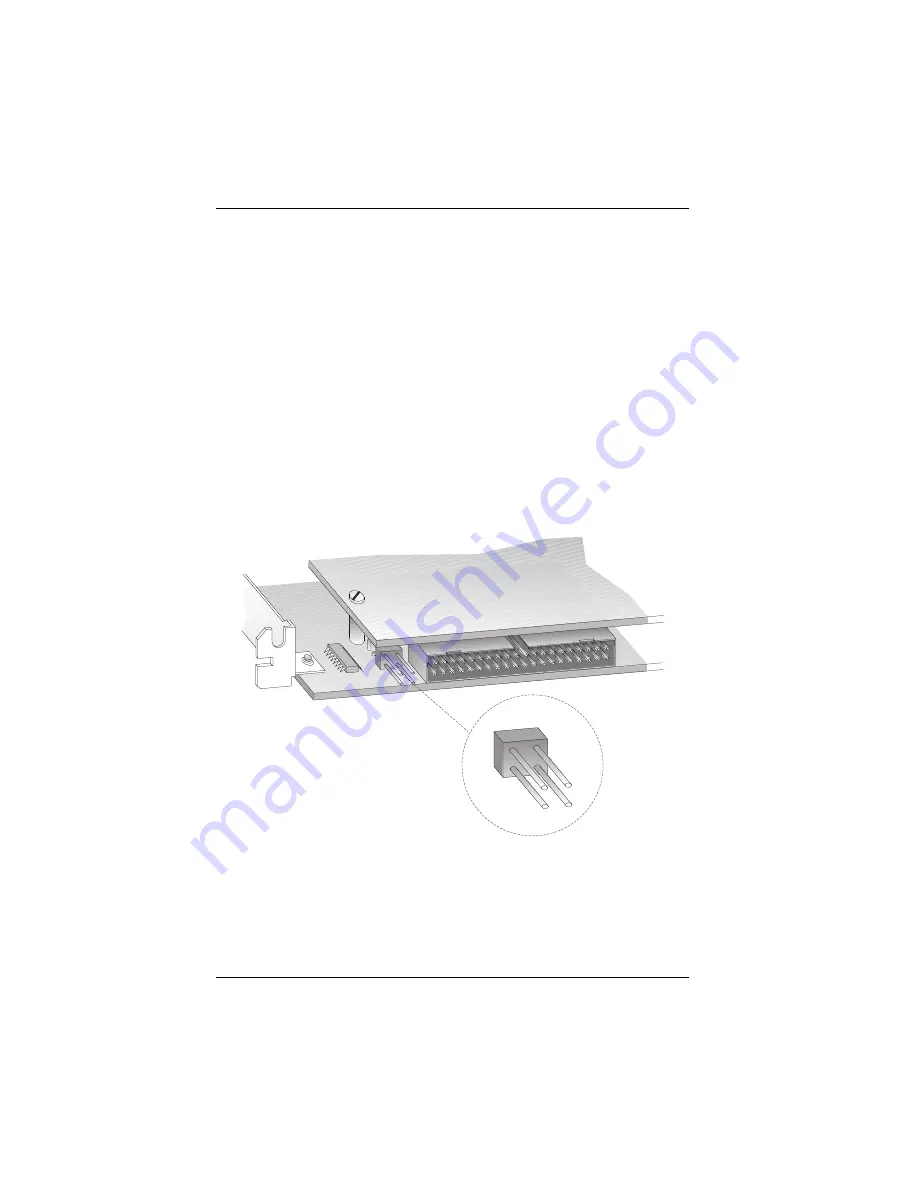
place two jumpers on the two 2-pin connectors located next to 
the MVIP connector, as described in the following figure.

Figure 2-5.  Electrically Terminating the MVIP Bus.

Содержание iSPAN 5535 PRI

Страница 1: ...iSPAN 5535 PRI PCI ISDN Adapter Users Guide Document No UG05535 000 REVB2 Print Date July 2002 ...

Страница 2: ...NOTE See Appendix I for Regulatory Statements Conditions that affect the operation of this product The CE Declaration of Conformity can be found at www iphase com ...

Страница 3: ...rmation obtained from this manual Interphase Corporation reserves the right to revise this manual without obligation to notify any person of such revision Information available after the printing of this manual will be in one or more Read Me First documents Each product shipment includes all current Read Me First documents All current Read Me First documents are also available on our web site THIS...

Страница 4: ...urchased Directly from Interphase Corporation Contact Interphase Corporation directly for assistance with this or any other Interphase Corporation product Please have your purchase order and serial numbers ready Customer Service United States Telephone 214 654 5666 Fax 214 654 5500 E Mail intouch iphase com Europe Telephone 33 0 1 41 15 44 00 Fax 33 0 1 41 15 12 13 World Wide Web http www iphase c...

Страница 5: ...local Interphase representative for service and repair to ensure that safety features are maintained Ground the Instrument To minimize shock hazard the equipment chassis and enclosure must be connected to an electrical ground The power cable must either be plugged into an approved three contact electrical outlet or used with a three contact to two contact adapter with the grounding wire green firm...

Страница 6: ...be used in a host system with a screw down cover lid in order to protect the operator Telephone Wiring Warnings Never install telephone wiring during a lightning storm Never install telephone jacks in wet locations unless the jack is specifically designed for wet locations Never touch non isolated telephone wires or terminals unless the telephone line has been disconnected at the network interface...

Страница 7: ...NG This equipment generates uses and can radiate electromagnetic energy It may cause or be susceptible to electromagnetic interference EMI if not installed and used in a cabinet with adequate EMI protection ...

Страница 8: ...ot use this software on any non Interphase product LICENSEE MAY NOT RENT LEASE LOAN OR RESELL THE SOFTWARE OR ANY PART THEREOF Ownership of Software Interphase or its vendors retain all title to the Software and all copies thereof and no title to the Software or any intellectual property in the Software is being transferred Software Transfer You may permanently transfer all of your rights under th...

Страница 9: ...its vendors Licensee agrees to maintain the Software in confidence and not to disclose the Software to any third party without the express written consent of Interphase Licensee further agrees to take all reasonable precautions to prevent access to the Software by unauthorized persons Termination Without prejudice to any other rights Interphase may terminate this Agreement if you fail to comply wi...

Страница 10: ...s Agreement is held invalid illegal or unenforceable the remaining provisions shall in no way be affected or impaired thereby All rights in the Software not specifically granted in this Agreement are reserved by Interphase ...

Страница 11: ... Product Features 3 Minimum System Requirements 4 Software Drivers 5 CHAPTER 2 Installing the Hardware Overview 7 Verifying Minimum Requirements 7 Inspecting the Adapter 7 Installing the Adapter 9 Connecting the Adapter to an MVIP Bus 14 Requirements for MVIP Bus Electrical Termination 15 How to Configure MVIP Electrical Termination on the iSPAN PRI 16 CHAPTER 3 Connecting to the Line Overview 17 ...

Страница 12: ...25 CHAPTER 4 Installing the Software Overview 27 Verifying Minimum Requirements 27 Installing and Setting Up the Drivers 28 Setting up RAS Support Properties 36 Setting Up ISDN B Channels as RAS Ports 38 Checking the ISDN Line with LoopTest 43 Removing the Drivers 46 CHAPTER 5 Setting Up WAN Firmware and Hardware Overview 51 Accessing Online Help 51 Managing Firmware and Hardware 52 Firmware Manag...

Страница 13: ...d Possible Solutions 72 APPENDIX A Specifications Adapter Specifications 77 Operating Environment 77 Storage Environment 78 APPENDIX B Using the SynWatch Utility Overview 79 Accessing Online Help 80 Starting SynWatch 80 Mouse Button Functions 82 Watching ISDN Channels 82 Watching the ISDN D Channel 82 Watching ISDN B Channels 84 Watching ISDN Layer 1 Alarms 85 Stopping and Freezing the Display 86 ...

Страница 14: ...er 97 RasTracker 98 Routing and Remote Access Service 98 APPENDIX E Using the LineTest Utility Overview 101 Accessing Online Help 101 Determining the Current Port Mode 102 Setting Port and Clock Modes 102 Loopback Mode 104 PRBS Generator and Monitor Mode 105 Operational Mode 106 Clock Modes 106 APPENDIX F Using the LineStatus Utility Overview 109 Accessing Online Help 109 Interpreting LineStatus I...

Страница 15: ...w 115 Index of Common Tasks 115 Procedures 116 APPENDIX H ISDN Technology Overview Overview 125 Basic Rate Interface 125 Primary Rate Interface 126 APPENDIX I Regulatory Statements FCC 127 Canada 129 Europe 131 EN60950 IEC950 Security Standard 132 Accessory 132 Glossary 133 Index 143 ...

Страница 16: ...vi Interphase Corporation ...

Страница 17: ...gy in addition to what this manual provides see the following web sites ISDN links http www bellcore com nic http www via isdn org http www comware com telcom telcolnk htm Networking glossary http www ctcnet com tips glossary htm Icon Conventions Icons draw your attention to especially important information such as the following NOTE The Note icon indicates important points of interest related to ...

Страница 18: ...e surrounding environment Text Conventions The following conventions are used in this manual Computer generated text is shown in typewriter font Examples of computer generated text are program output such as the screen display during the software installation procedure commands directory names file names variables prompts and sections of program code Example of computer generated text Commands to ...

Страница 19: ...ther pointer and click on the Products option A menu will appear on the left side with Telecom Solutions Enterprise Solutions and Services options Choose the appropriate menu item such as PowerSAN Fibre Channel HBAs 3 A new web page with a list of the currently offered products will appear Choose your product by clicking on the product number i e 4532 5540 4575 etc 4 The Product Description page a...

Страница 20: ...to determine if updated drivers are available for your product When contacting technical support please be sure to provide your name company name and address phone number product name driver version if applicable OS and version if applicable and serial number Providing this information will help speed up our response ...

Страница 21: ...ms to connect to one or two ISDN primary rate interfaces The single PRI version is powered by the IBM PowerPC 403GA 32 bit RISC processor at 33 MHz The dual PRI version is powered by the IBM PowerPC 403GCX 32 bit RISC processor at 66 MHz and combined with a 32 bit 33 MHz PCI interface It provides a fast pathway to enterprise communication server applications Figure 1 1 iSPAN PRI PCI ISDN Adapter D...

Страница 22: ...X SPX and NetBEUI protocols RAS supports all of the mainstream networking clients including the following Windows for Workgroups LAN Manager Windows 95 Windows NT Workstations Windows NT Servers UNIX Macintosh NetWare OS 2 based clients RAS connection enables all services typically available to a LAN connected user including file and print sharing database access and messaging as shown in the foll...

Страница 23: ...DN Compatibility NET3 E DSS1 NI 1 NI 2 Conforms to all industry standards and specifications FCC part 15 class A and part 68 CE class A IEC950 Single PRI version 32 bit RISC processor PowerPC 403GA 33 MHz 4 MB dual port DRAM memory and 128 KB Flash EEPROM RAS support for up to 30 B channels and 1 D channel Europe or 23 B channels and 1 D channel United States and Japan ...

Страница 24: ...l plug and play installation Minimum System Requirements The minimum system requirements for using this adapter with Microsoft Remote Access Service RAS are An Intel system running Windows NT Version 4 0 either Workstation or Server Bus architecture PCI Local Bus Specification Revision 2 1 Processor Pentium at 133 MHz 32 MB RAM you may need up to 128 MB depending on your RAS configuration and usag...

Страница 25: ...r requires the following drivers WAN adapter driver for Windows NT the basic driver required to support the adapter RAS Support the driver required to support Microsoft Remote Access Service over ISDN Enables the transport of TCP IP IPX SPX and NetBEUI protocols over ISDN lines These drivers are both installed during the installation procedure The general software architecture is as follows Figure...

Страница 26: ...Software Drivers 6 Interphase Corporation The complete iSPAN PRI software is stored on a single diskette or a CD ROM included in the adapter package ...

Страница 27: ...he adapter to an MVIP Bus if required The tools required are a grounding strap and a 1 Phillips head screwdriver Both are delivered with the product and are included in the packaging Verifying Minimum Requirements Before installing this adapter verify that your system meets the minimum requirements described in Minimum System Requirements on page 4 Inspecting the Adapter Before installing the adap...

Страница 28: ... a grounding strap on your wrist or ankle and handle the adapter only by its edges Do not touch its components or any metal parts other than the faceplate If your adapter is a fiber adapter do not remove the connector cap s until you re ready to install the adapter 1 Open the shipping container and carefully remove its contents 2 Inspect each item for damage If you find any omissions or damage con...

Страница 29: ...s in this installation procedure both to protect yourself and prevent damage to your computer Use only tools with nonconductive handles or tools coated with covered with or made with nonconductive materials Nonconductive materials are materials that do not conduct electric current such as With a grounding strap connected to your wrist or ankle do the following to install the adapter ...

Страница 30: ... 1 Turn off the computer s power switch and unplug the unit from its power source Figure 2 1 Unplugging the Computer 2 Disconnect all cables connected to the main system unit and remove the computer cover according to the manufacturer s instructions ...

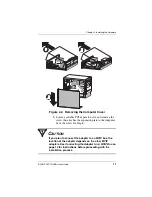
Страница 31: ... slot and remove the screw that attaches the expansion plate to the computer Save the screw for Step 6 CAUTION If you plan to connect the adapter to an MVIP bus the location of the adapter depends on the other MVIP adapters See Connecting the Adapter to an MVIP Bus on page 14 for instructions before proceeding with the installation process ...

Страница 32: ...Installing the Adapter 12 Interphase Corporation 4 Remove the expansion plate Figure 2 3 Removing the Expansion Plate ...

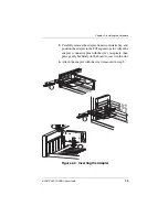
Страница 33: ...apter from its antistatic bag and position the adapter in the PCI expansion slot Align the adapter s connector pins with the slot s receptacle then press gently but firmly on the board to seat it in the slot 6 Attach the adapter with the screw removed in step 3 Figure 2 4 Inserting the Adapter ...

Страница 34: ...cting to the Line on page 17 Connecting the Adapter to an MVIP Bus You must connect the adapter to an MVIP bus if you plan to integrate the adapter with other MVIP telephony processing adapters such as voice data fax video or image processing adapters To create a dedicated interconnection between these adapters connect a ribbon cable to the 40 pin double row right angled headers on the top edge of...

Страница 35: ...e network In this case place the iSPAN PRI adapter at one end of the cable On systems with more than five MVIP bus connections or more than 90 pF of load on the clock lines both ends of the cable must be electrically terminated No other boards should be electrically terminated If the iSPAN PRI adapter is at one of the MVIP cable ends you must set the dip switches to their ON position down to compl...

Страница 36: ...t have to be electrically terminated do not insert any jumpers into the 2 pin connectors If this is the last board in a multiple MVIP bus configuration the iSPAN PRI adapter requires electrical termination in the MVIP bus To provide the required electrical termination place two jumpers on the two 2 pin connectors located next to the MVIP connector as described in the following figure Figure 2 5 El...

Страница 37: ...o connect the adapter to the network If you are in North America continue with the next section If you are in Europe skip to European E1 PRI Line on page 23 North America T1 PRI Line When you connect the adapter to a North American T1 PRI line first determine the appropriate connection method cabling requirements and link requirements Two T1 PR1 line configurations exist DSX1 short haul and DS1 lo...

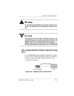
Страница 38: ...too long you will need to connect the adapter to an external CSU which itself will be connected to the metallic T1 PR1 interface Connecting directly to the line without a CSU You can connect the iSPAN PRI directly to the line without any internal or external CSU if the distance to your carrier is short enough less than 655 feet or 200 meters The line will be in a DSX1 configuration short haul See ...

Страница 39: ...r to disconnecting the adapter from the line or turning off the power to the adapter s host system Without this prior notification the carrier might temporarily discontinue your T1 PRI service Connecting directly to the line with an internal CSU If your iSPAN PRI adapter includes the internal CSU option you can connect it directly to the line and be up to 6200 feet 1 8 km far from your carrier The...

Страница 40: ...ning off the power to the adapter s host system Without this prior notification the carrier might temporarily discontinue your T1 PRI service Connecting to the line through an external CSU If the distance to your carrier is longer than 655 feet 200 meters or if your carrier does not accept a direction DSX1 connection and if your iSPAN PRI adapter does not include an internal Channel Service Unit C...

Страница 41: ... your carrier for approval before connecting the CSU to the line CAUTION In accordance with FCC Rules Part 68 218 b you must notify the telephone company prior to disconnecting the CSU from the line or turning the CSU s power off Without this prior notification the carrier might temporarily discontinue your T1 PRI service ...

Страница 42: ... cable length between the adapter and the carrier must be measured and recorded you will need this information The cable must include an RJ48C plug at the end dedicated to the WAN adapter It must also provide the appropriate plug or cabling system at the end connected to the carrier or CSU See Connector Pinouts on page 24 and relevant carrier or CSU documentation for more information T1 Link Requi...

Страница 43: ...d Generally your E1 PRI carrier provides a Network Termination 1 NT1 device to interface between the WAN adapter and the metallic interface of the WAN You need to connect the WAN adapter to the NT1 E1 PRI Cabling Requirements WARNING Before connecting the cable read Telephone Lines Unsafe Voltages in the Safety Precautions section at the front of this manual The cable between the adapter and the N...

Страница 44: ...equirements To interoperate successfully the adapter and the NT1 must be configured with several common E1 settings The adapter s E1 parameters are in accordance with the IUT T I 431 recommendation as follows Line coding HDB3 according to IUT T G 703 Frame format according to IUT T G 704 CRC4 to Non CRC4 operation according to IUT T G 706 An B Line I O impedance 120 Ohm 5 Connector Pinouts The fol...

Страница 45: ...Connecting the Adapter to the Network With the adapter installed you are ready to connect the adapter to the network as follows 1 Obtain the cable required for your type of connection as described in T1 Link Requirements on page 22 or E1 PRI Cabling Requirements on page 23 2 Attach the appropriate RJ48C compliant connector to the adapter 1 2 3 4 5 6 7 8 Pin Tx out tip Tx out ring Rx in ring Rx in ...

Страница 46: ...he Adapter to the Network 26 Interphase Corporation 3 Reconnect the power cable and turn on the machine After connecting the adapter to the network install the adapter drivers See Installing the Software on page 27 ...

Страница 47: ...w these basic steps 1 Verify that your system meets minimum requirements 2 Install and set up the drivers This chapter also explains how to remove the drivers if required If Read Me First documentation is included in your installation kit review it before installing the driver It may contain changes and updates made to this users guide after the print date Verifying Minimum Requirements If you hav...

Страница 48: ...t utility NOTE The iSPAN PRI adapter is called either 5535 1P PRI or 5535 2P PRI in the software installation and configuration Installing the Drivers Before you start make sure the adapter is installed in your machine and that you are logged on with administrator rights to the Windows NT 4 0 system To install the WAN and RAS support drivers for the adapter 1 From the Start menu select Settings an...

Страница 49: ...Chapter 4 Installing the Software iSPAN PRI PCI ISDN Users Guide 29 Figure 4 1 Network Identification tab of the Network dialog 2 Select the Adapters tab to display the Adapters dialog ...

Страница 50: ... Setting Up the Drivers 30 Interphase Corporation Figure 4 2 Network Adapters tab of the Network dialog 3 Click Add to begin loading the drivers The system creates an adapter list in the Select Network Adapter dialog ...

Страница 51: ...the Software iSPAN PRI PCI ISDN Users Guide 31 Figure 4 3 Network Adapters List 4 Click Have Disk The Insert Disk dialog appears prompting you to insert the disk and identify the file location Figure 4 4 Insert Disk dialog ...

Страница 52: ... letter assigned to the CD ROM drive change it to D 5535PRI or select the appropriate drive and click OK The Select OEM Option dialog appears with 5535 INTERPHASE RAS Support selected Figure 4 5 Select OEM Option dialog 6 Click OK to confirm the selection The INTERPHASE WAN Adapter driver window appears prompting you to accept or change the installation directory and begin installation You can ins...

Страница 53: ...eded change the default installation path in the Copy To field to the desired pathname 8 Click Continue to install the driver The installation program copies product files to the directory specified in the Copy To field and creates a program group in the Windows NT Start menu Next the WAN Adapters setup dialog appears ...

Страница 54: ...matically detected The Cards list should be updated to include the iSPAN PRI adapter listed as a version of the 5535 in your machine NOTE If the cards list is empty the adapter might not be properly installed Click OK Then see Problems and Possible Solutions on page 72 for information about correcting the problem ...

Страница 55: ...play the ISDN PRI Port Properties dialog Figure 4 8 ISDN PRI Port Properties b Select the switch type that corresponds to your ISDN subscription and click OK For more information about switch types see Setting Up ISDN PRI Port Properties on page 56 c When the WAN Adapters setup dialog reappears repeat steps a and b for each ISDN PRI port d When all ISDN ports are configured click OK The configurat...

Страница 56: ...p Message To continue the software installation set up RAS support properties as described in the next section Setting up RAS Support Properties After you respond OK to the message that the driver is running the Interphase 5535 RAS Support dialog appears Figure 4 10 RAS Support Setup This dialog enables you to set up RAS Support properties for the adapter ...

Страница 57: ...ort list in RAS setup Then skip to Setting Up ISDN B Channels as RAS Ports on page 38 If Remote Access Service is not yet installed on your system a message informs you that RAS support setup is complete and states that Remote Access Services RAS setup must now be installed Click OK and continue to step 2 2 When a message informs you that Setup needs to copy Windows NT files enter the complete pat...

Страница 58: ...o continue the software installation set up ISDN B channels as RAS ports as described in the next section Setting Up ISDN B Channels as RAS Ports After RAS is installed you can set up ISDN B channels as RAS ports using the Add RAS Device dialog Figure 4 12 Add RAS Device This dialog appears after you respond OK to the message that Remote Access Service must be invoked or that Remote Access Service...

Страница 59: ...s Setup dialog appears with the ISDN port included in the RAS port list Figure 4 13 Remote Access Setup 2 Select the port and click Configure to set up its connection mode The Configure Port Usage dialog appears Figure 4 14 Configure Port Usage 3 Select a port usage option and click OK ...

Страница 60: ...onfigure all ISDN channels with the same port usage as the first ISDN channel a Click Clone until a message informs you there are no more ports of the specified type to clone b Click OK 5 When the Remote Access Setup dialog reappears do the following to select the protocols NetBEUI TCP IP or IPX and other settings to be bound to the adapter a Click Network to display the Network Configuration dial...

Страница 61: ... to allow multiple ISDN B channels to make one logical network connection This function aggregates several ISDN B channels to increase the bandwidth of PPP links For more detailed network configuration information see Microsoft s online help for RAS b Click OK to confirm your network configuration c When the Remote Access Setup dialog reappears click Continue ...

Страница 62: ...rt adapter now appears in the Network Adapters list on the Adapters dialog Figure 4 16 Network Adapters List 7 Click Close to complete the software installation After the software is fully installed a message informs you that you must shut down and restart your computer before the settings take effect ...

Страница 63: ... a Service Pack is installed see Index of Common Tasks on page 115 8 If the system is a Windows NT basic system with no service pack installed click Yes to restart the computer Otherwise click No Then reinstall the Windows NT Service Pack before restarting the system Next continue the software installation by checking the ISDN line as described in the next section Checking the ISDN Line with LoopT...

Страница 64: ...erver as follows a From the Start menu select Programs then Administrative Tools Common and then Remote Access Admin The following dialog appears Figure 4 17 Remote Access Admin Dialog b From the Server menu select Stop Remote Access Service 2 After the RAS server is stopped from the Start menu select Programs then INTERPHASE WAN Adapters and then LoopTest The LoopTest dialog appears ...

Страница 65: ...est passed in the Diagnostic field If the Test passed message does not appear make sure that the ISDN number you entered is correct For more information about the LoopTest utility and its diagnostics see Using the LoopTest Utility on page 89 5 Do the following to enable the RAS Server again a From the Start menu select Programs then Administrative Tools Common and then Access Admin b From the Serv...

Страница 66: ...S Dial Up Networking see the following For an overview see Index of Common Tasks on page 115 For detailed information see Microsoft RAS online help Removing the Drivers If you no longer use the adapter do the following to remove the WAN and RAS Support drivers 1 Be sure you are logged on with administrator rights to the Windows NT 4 0 system 2 From the Start menu select Settings and then Control P...

Страница 67: ...igure 4 19 Network Adapters List 3 Select INTERPHASE 5535 RAS ISDN support for the iSPAN PRI and click Remove A warning message informs you that this action will permanently remove the component and asks if you want to continue 4 Click Yes to continue the driver removal ...

Страница 68: ...er 6 Confirm your choice by clicking Yes when a pop up asks you to confirm the card s removal and driver deletion After you confirm the deletion the system does the following Deletes product files and the WAN Adapter program group from the Start menu Dynamically unloads the drivers from memory Cleans up the registry When the deinstallation process is finished the Adapters dialog reappears 7 Click ...

Страница 69: ... system Click OK to complete the driver deletion NOTE When the system boots up again the Remote Access Service will fail to initialize As a result RAS errors will appear in the Windows NT Event Viewer To avoid this problem uninstall Remote Access Service after you uninstall the adapter as described in Microsoft documentation and online help Then restart your computer 9 When a message informs you t...

Страница 70: ...Removing the Drivers 50 Interphase Corporation ...

Страница 71: ...ts The chapter explains how to do the following WAN Adapter Setup tasks Access online help Manage adapter firmware and hardware Set up ISDN properties Accessing Online Help For detailed information about the functions described in this chapter see the WAN Adapter Setup online help You can access online help in the following ways Click Help to display the main online help Press F1 to display contex...

Страница 72: ...n WAN Adapter Setup dialogs Start the WAN Adapter Setup utility in either of the following ways From the Start menu select Settings and then Control Panel Then double click the WAN Setup icon From the Start menu select Programs then INTERPHASE WAN Adapters and then WAN Setup When you start the utility the WAN Adapters Setup dialog appears ...

Страница 73: ...section is for firmware management The Cards section is for hardware management Firmware Management The Microcode section of the Wan Adapter Setup dialog displays firmware information for the currently selected WAN adapter It displays the protocols you can use with the adapter and their status You can view the microcode status reload the microcode or change the microcode ...

Страница 74: ...rotocol as follows LED Color For General LED For Individual LEDs Red No microcode is found on the disk for the current card N A Gray Microcode is found but is not loaded into the card The protocol is inactive Yellow Microcode is running on the card but is different from that found on the disk for this card N A Green The microcode is running The protocol is active ...

Страница 75: ...ed in the machine their status and their available communication ports The Click To do this Load Download the current microcode to the selected adapter CAUTION CAUTION This option disconnects all current RAS connected users and disables the RAS Server After a microcode download the RAS Server must be re enabled as follows 1 From the Start menu select Programs then Administrative Tools Common and t...

Страница 76: ...N line first obtain the ISDN switch type from your ISDN provider LED Color Meaning Gray The adapter is detected but is not working Yellow The hardware configuration has been changed but not applied Green The adapter is running Click To do this Add Add a new adapter This option is enabled if one more Interphase adapters can be installed Remove Remove an existing adapter This option removes an adapt...

Страница 77: ... shown in Figure 5 1 on page 53 2 Click the Properties button in the Cards section The ISDN PRI Port Properties dialog appears Figure 5 2 ISDN PRI Port Properties Configuring the Switch Type In the ISDN PRI Port Properties dialog select one of the following switch type settings depending on your location and your ISDN provider s switch type In North America select one of the following switch types...

Страница 78: ...rt Properties dialog shown in Figure 5 2 on page 57 The CRC type depends on the switch type whether E1 or PRI and the country For European countries other than France select CRC4 For France deselect CRC4 Editing DS1 Properties North America Only If you have selected an American Switch Type you can edit the DS1 properties on the DS1 Properties dialog To display the DS1 Properties dialog 1 Select th...

Страница 79: ...ide 59 NOTE The Edit DS1 Properties button is enabled only when an American Switch Type is selected The DS1 Properties dialog appears Figure 5 3 DS1 Properties Line framing CRC and Line code parameters describe physical level parameters which cannot be modified on a PRI Line ...

Страница 80: ...ion An external CSU is not required Deselect Activate the CSU to deactivate a CSU between the network and the adapter The CSU facility is protected by a password You must enter this password when selecting Activate the CSU for the first time For password instructions refer to the Read Me First information provided in your adapter package Network Line Build Out The Network line build out compensate...

Страница 81: ...sued by the Telco to put the adapter in loopback mode for testing when problems occur They are also used to transmit statistics about physical transmission errors on the line Two protocols are available for the facility data link the ANSI T1 403 and the ATT 54016 protocol Both are compatible with each other Use the protocol s indicated by your Telco If this information is unavailable the best choi...

Страница 82: ...Setting Up ISDN PRI Port Properties 62 Interphase Corporation ...

Страница 83: ...o the following Ras Support Setup tasks Access online help Determine RAS Support parameters Accessing Online Help For detailed information about the functions described in this chapter see the RAS Support Setup online help You can access online help in the following ways Click Help to display the main online help Press F1 to display contextual help in a pop up window Move the cursor over a window ...

Страница 84: ...iSPAN PRI is listed as the 5535 in RAS Support Setup dialogs To access the RAS Support Setup dialog 1 From the Start menu select Settings and then Control Panel 2 Double click the Network icon and then select the Adapters tab 3 On the Adapters dialog select INTERPHASE 5535 RAS ISDN support for the iSPAN PRI from the adapters list and click Properties The Interphase 5535 RAS Support dialog appears ...

Страница 85: ...means that the driver is running and gray means that it is not running The numeric suffix in the name in this case 3 is the logical network adapter number assigned by Windows NT Idle Timeout The Idle timer is an inactivity timer It is used to disconnect an ISDN connection when no data traffic is exchanged This timer setting is attached to the displayed adapter The setting is identical for all of t...

Страница 86: ...Determining RAS Support Parameters 66 Interphase Corporation ...

Страница 87: ...talling and setting up the hardware and the software and have rebooted the system Also check the system log to see what kind of errors if any are being recorded If the information in this chapter does not resolve the problem contact Interphase Technical Support at one of the locations listed in the Assistance section at the front of this Users Guide Interpreting Adapter LEDs The iSPAN PRI provides...

Страница 88: ...CRC type North America In North America the adapter LEDs for each port function are as follows In their operational state the LEDs must be as follows LED Color Meaning if the light is ON 1 Green Clock is synchronized 2 Green Physical layer is active 3 Yellow Your ISDN provider is currently sending an RAI alarm to the adapter 4 Red Loss Of Signal LOS indicating no electrical power is detected on th...

Страница 89: ...g On On Off Off Adapter is operational On On On Off A synchronization problem occurred on the ISDN carrier side Off Off Off On No power is detected on the line Make sure cable is plugged in correctly Off Off Off Off Your ISDN provider is currently sending an AIS alarm to the adapter LED Color Meaning if the light is ON 1 Green Clock is synchronized 2 Green Physical layer is active 3 Yellow Your IS...

Страница 90: ...I Port Properties on page 56 On Off On Off Remote Alarm Indication RAI Your ISDN provider has synchronization problems and is reporting this problem to you On Off Off On Your E1 PRI line does not support CRC4 functionality Deselect the CRC4 option See Setting Up ISDN PRI Port Properties on page 56 Off Off Off Off No electrical signal is on the E1 PRI line Make sure your cable is plugged in correct...

Страница 91: ...1 LED2 LED3 LED4 Meaning On On Off Off Adapter is operational On Off On Off Your E1 PRI line requires CRC4 Select the CRC4 option See Setting Up ISDN PRI Port Properties on page 56 On Off Off Off Your E1 PRI line requires CRC4 Select the CRC4 option See Setting Up ISDN PRI Port Properties on page 56 Off Off Off Off Either no electrical signal is on the E1 PRI line or your ISDN provider is currentl...

Страница 92: ...he Hardware on page 7 3 If the WAN Adapter Setup still cannot detect the adapter see Computer does not boot up or Host adapter not found on page 73 When the adapter is installed continue as follows 1 From the Start menu select Programs then INTERPHASE WAN Adapters and then WAN Setup 2 Click Add on the main dialog and do the following as instructed in Installing the Software a Configure the adapter...

Страница 93: ...es the switch the adapter is using 3 Check the phone number 4 For more detailed information see Understanding LoopTest Messages on page 94 RAS Dial out failed The following possible solutions assume a successful LoopTest If you do not know how to check the following items see Index of Common Tasks on page 115 1 Check to see whether at least one ISDN RAS port is configured to make outgoing calls 2 ...

Страница 94: ...y the remote user IP IPX SPX or NetBEUI are configured in the RAS server 6 Use SynWatch to see if an ISDN connection problem exists Does SynWatch see the ISDN call in progress Is this call accepted by the remote system 7 Use SynWatch to see if a PPP negotiation problem exists Check the remote user ID and password Multilink is not enabled in the RAS phonebook entry properties Select the Enable Mult...

Страница 95: ...installed correctly See Index of Common Tasks on page 115 2 In the WAN Adapter Setup program check that the ISDN Layer is present in the adapter microcode CSU activation failed at load time If a message appears at load time informing you that the CSU activation failed you probably entered an invalid password for CSU activation Enter the password again to activate the CSU and reload See Editing DS1...

Страница 96: ...Problems and Possible Solutions 76 Interphase Corporation ...

Страница 97: ... Revision 2 1 PCI Form Factor Length 174 6 mm Width 106 7 mm Depth 17 2 mm Host Data Transfer Adapter with 2 PRI ports 8MB dual port DRAM Adapter with 1 PRI port 4MB dual port DRAM Optional Functions 32 bit 33 MHz local bus Operating Power 1 3A maximum 5 0 VDC Temperature 0 55 C 32 131 F Relative humidity 10 95 noncondensing Altitude 0 15 000 feet ...

Страница 98: ...Storage Environment This section assumes the adapter is stored in its original anti static bag and box Temperature 20 85 C 4 185 F Relative humidity LAN and storage adapters 10 95 noncondensing WAN adapters 5 95 noncondensing Altitude 0 50 000 feet ...

Страница 99: ...atch provides diagnostics for ISDN connection failures It helps you detect PPP connection failures for example PPP negotiation using Remote Access Service SynWatch interprets exchanged frames according to several protocols Remote Access Service uses the PPP protocol It displays these frames according to the appropriate protocol This appendix explains how to do various SynWatch tasks such as Access...

Страница 100: ... Use the menu command Help to display the main online help Press F1 to display contextual help in a pop up window Move the cursor over a window control to display a pop up with the name of the control Starting SynWatch NOTE The iSPAN PRI is listed as the 5535 adapter in SynWatch dialogs To start Synwatch from the Start menu select Programs then INTERPHASE WAN Adapters and then SynWatch The main Sy...

Страница 101: ...ivate or deactivate frame watching The right side is the monitor panel It displays exchanged frames The configuration panel displays the adapter description in a tree view with the following levels First level Name of the computer Second level Adapter Third level Ports available on an adapter Fourth level Channels available on a port Each port has one ISDN D channel and 23 ISDN B channels on an Am...

Страница 102: ...diagnostic information about Left click the checkbox beside the channel to activate or deactivate frame watching for that channel To select or deselect all of a port s channels left click the checkbox beside the port To select or deselect all of an adapter s ports left click the checkbox beside the adapter When you choose to activate frame watching a list of watch modes appears After you select a ...

Страница 103: ...D channel 1 Select the channel in the configuration panel of the Synwatch dialog A list of watch modes appears Figure B 2 ISDN D Channel Watch Modes 2 To activate frame logging select one of the watch modes Select LAPD to see detailed descriptions of signalling frames Select LAPD reduced to see brief descriptions of signalling frames Select Hexadecimal Dump to see Hexadecimal dump of signalling fr...

Страница 104: ...established The first few data frames exchanged between local and remote sites correspond to a second connection phase to allow the establishment of the upper layer for example the PPP protocol 1 To activate watching on one ISDN B channel select that channel in the configuration panel of the SynWatch dialog To activate watching on all ISDN channels select the PRI port related to the adapter Port 0...

Страница 105: ... Relay SDLC QLLC Hexadecimal Dump For detailed information about each watch mode see SynWatch online help Watching ISDN Layer 1 Alarms ISDN Layer 1 alarms are managed by the adapter and are activated when physical events occur To display these alarms using SynWatch 1 In the Configuration panel of the SynWatch dialog right click the PRI port for which to display alarms 2 Select to enable Layer 1 al...

Страница 106: ...e Watch menu select Freeze To resume display at the point where it stopped deselect Freeze from the Watch menu Changing the Watch Mode SynWatch can reinterpret all frames displayed in the monitor panel into another protocol You can change the watch mode enabling SynWatch to reinterpret the frame protocol Here is an example of when it is useful to change the watch mode if the ISDN D channel is in L...

Страница 107: ...aningful and easier to read If you want SynWatch to reinterpret an ISDN channel s frame information right click on a channel and change the watch mode as required Editing ISDN Channel Settings The monitor panel displays information about each exchanged frame listed in text lines in the monitor panel You can define different display fonts and or color s for each ISDN channel To change the font or c...

Страница 108: ...ates the monitor panel with your new settings immediately Saving and Editing Frames You can use the SynWatch Save option to save all frame information recorded in the monitor panel as an ASCII text or binary file You can read a text file using any text editor but SynWatch cannot read or reinterpret the text file On the other hand SynWatch can read or reinterpret a binary file ...

Страница 109: ...l is set up to accept incoming calls and the other channel calls the first channel When the connection is established the calling channel sends data which is checked when it gets to the receiving channel At the end of the test LoopTest stops the communication If an error occurs during testing LoopTest displays a warning and stops the communication at that point This appendix explains how to perfor...

Страница 110: ...up window Move the cursor over a window control to display a pop up with the name of the control Testing your ISDN Line To check your ISDN line do the following 1 Before executing the LoopTest and to avoid incoming call conflicts disable the RAS Server as follows a From the Start menu select Programs then Administrative Tools Common and then Remote Access Admin The following dialog displays inform...

Страница 111: ...t from the drop down list if your adapter has two PRI ports and enter your own ISDN number 4 Click Test The diagnostic field describes the test result If the message Test Passed appears your ISDN line is working and RAS dial in or dial out can be done If an error occurred LoopTest displays information about the cause and circumstances of the error For more detailed information about these messages...

Страница 112: ... select Programs then Administrative Tools Common and then Remote Access Admin b From the Server menu select Start Remote Access Service c If Windows NT does not display the name automatically enter the server name preceded by two backslashes To determine the server name see Index of Common Tasks on page 115 d Click OK Displaying and Saving Events The event list is an additional window at the bott...

Страница 113: ...he Test menu Setting the Number of Frames to Send You can set the number of frames you want LoopTest to send during communication To set the number of frames to send 1 Access the LoopTest main dialog as described in step 2 of Testing your ISDN Line on page 90 2 Select the Parameters option from the Test menu to display the Test Parameters dialog Figure C 3 LoopTest parameters 3 Enter the number of...

Страница 114: ...ssages Message Cause Test passed LoopTest detected no errors during testing Card missing or non ISDN An error occurred before accessing the network Possible causes are The adapter is not installed The drivers are not properly installed LoopTest could not find an ISDN port on the adapter To check for ISDN ports a From the Start menu select Programs then INTERPHASE WAN Adapters and then WAN Setup b ...

Страница 115: ... the microcode is loaded LEDs must be green and check its characteristics ISDN layers must appear Driver access denied This error occurs in the following situations You are executing more than the maximum 15 instances of LoopTest The driver is not installed or is improperly installed Connection failed The connection cannot be established and the ISDN network has not supplied a reason This error ge...

Страница 116: ...r end OR ERROR A bad pattern has been received frame number When the connection is established the test sends a pattern on one B channel and should receive it on the other B channel This message occurs when the pattern is lost or invalid Possible causes are The test application might be connected to another application The ISDN number might be wrong An incoming call from another application arrive...

Страница 117: ...ager from NTP Software is a client server application that provides full time control real time monitoring and session by session accounting for RAS connections on a user by user basis RAS Manager enables you to Establish and automatically enforce a RAS management policy Generate RAS use information for your corporate charge back system Allow or deny RAS access to users Control the length of RAS s...

Страница 118: ...s allowed access Set a maximum connection time for per connection for a user Set a maximum total time for all of a user s connections For more information about RasTracker see Windows NT products at the following web site www optimus co uk Routing and Remote Access Service Routing and Remote Access Service RRAS from Microsoft Corporation provides advanced routing and internetworking capabilities I...

Страница 119: ... user interface and command line interface with scripting APIs for third party routing protocols user interface and management Demand dial routing PPTP server to server for secure Virtual Private Networks RADIUS client support For more information about RRAS see the following web site www microsoft com ...

Страница 120: ...Routing and Remote Access Service 100 Interphase Corporation ...

Страница 121: ... you can do low level testing This appendix explains how to do the following LineTest tasks Access online help Set port testing and clock modes Accessing Online Help For detailed information about the functions described in this appendix see the LineTest online help You can access online help in the following ways Use the Help menu command to display the main online help Press F1 to display contex...

Страница 122: ...art menu select Programs then INTERPHASE WAN Adapters and then LineTest The main LineTest dialog appears Figure E 1 LineTest Dialog On this dialog animated port icons and a text message provide a continuously updated status of the port mode Setting Port and Clock Modes To set port and or clock modes on the adapter 1 Access the LineTest dialog as described in step 1 of Determining the Current Port ...

Страница 123: ... 103 2 Click Select mode to display the Port Test Configuration dialog Figure E 2 Port Test Configuration Dialog 3 Select the appropriate port or clock mode for your testing or operating needs The following sections provide detailed information about setting these modes ...

Страница 124: ...alog shown in Figure E 2 on page 103 Two loopback settings are available Line loopback The signal returned to the loopback command source consists of the full signal Bit sequence integrity is maintained No change in framing occurs and no bipolar violations are removed This is the default loopback setting Payload loopback The signal returned to the loopback command source consists of the payload of...

Страница 125: ...nd Monitor mode causes a port to generate and transmit Pseudo Random Bit Sequences online while it tries to synchronize on the received signal CAUTION Use this mode only with Telco agreement Also when you use this mode make sure that remote equipment is set to loopback mode To select this mode select PRBS Generator and Monitor mode on the Port Test Configuration dialog shown in Figure E 2 on page ...

Страница 126: ...ure E 2 on page 103 Before closing the LineTest utility you are requested to restore each port in testing mode to the operational mode Clock Modes In some test configurations such as back to back configurations a port must use the remote adapter clock to successfully synchronize on the received signal Message Meaning No error The receiving bit sequences completed and the port found no errors when ...

Страница 127: ...st be in slave mode and the clock of the remote adapter must be in master mode which is the default clock type To set the clock mode 1 Click Options on the Port Test Configuration Dialog shown in Figure E 2 on page 103 The Port Options dialog appears Figure E 4 LineTest Options dialog 2 Select the clock setting you want to use ...

Страница 128: ...Setting Port and Clock Modes 108 Interphase Corporation ...

Страница 129: ... explains how to do the following access online help interpret alarm error loopback and statistics information Accessing Online Help For detailed information about the functions described in this appendix see the LineStat online help You can access online help in the following ways Use the Help menu command to display the main online help Press F1 to display contextual help in a pop up window Move...

Страница 130: ...pter port It notifies you of alarms errors loopback mode and statistics related to the port When a port is operating under normal conditions all LEDs are grey To view LineStatus information 1 From the Start menu select Programs next INTERPHASE WAN Adapters and then LineTest The main LineTest dialog appears Figure F 1 Main LineStatus dialog The following sections provide detailed information about ...

Страница 131: ...ars when many frames are lost because of framing errors The terminal is unable to synchronize on the DS1 signal AIS Alarm Indication Signal also known as Blue Alarm Transmitted instead of the normal signal to maintain transmission continuity Also indicates to the receiving equipment that a transmission interruption occurred either at the equipment originating the AIS signal or upstream of the orig...

Страница 132: ...bit error In ESF and E1 CRC formats a CRC error CS Controlled Slip Results from the replication or deletion of the payload bits of the DS1 frame A Controlled Slip may be performed when there is a timing difference between a synchronous receiving terminal and the received signal LED Meaning Payload The signal returned toward the source of the loopback command consists of the payload of the received...

Страница 133: ...conds that the interface is unavailable The DS1 interface is considered unavailable from the onset of 10 contiguous SESs or the onset of the condition leading to a failure Errored Seconds Also known as ES Number of seconds during which any the following have existed One or more PCV One or more LOF One or more CS Detected AIS defect Severely Errored Seconds Also known as SES For ESF signals number ...

Страница 134: ...Interpreting LineStatus Indicators 114 Interphase Corporation ...

Страница 135: ...Pack is installed 116 Determine the server name needed to start the Remote Access Server 116 Know which adapter s port is used when calling with an ISDN RAS port 117 See if the drivers are running 117 Open the Remote Access Setup 118 Bind a protocol to an ISDN RAS Port 118 Configure a RAS port to accept incoming calls 119 Configure a RAS port to dial out 119 Manage RAS incoming ports 119 Determine...

Страница 136: ...Do this Determine which version of the Windows NT Service Pack is installed 1 From the Start menu select Programs then Administrative Tools Common and then Windows NT Diagnostics 2 Select the Version tab The Service Pack currently installed is displayed just after the Windows NT version Determine the server name needed to start the RAS Server 1 From the Start menu select Settings and then Control ...

Страница 137: ...then Event Viewer The following messages must appear SynSV6 The Device Device SynSV6 has been successfully created Its symbolic link name is DosDevices SynSV6 SynSYS Adapter SynCard0 Opened SynSYS SynSys Driver Loaded 2 From the Start menu select Settings and then Control Panel 3 Double click the Devices icon The following devices must appear in the Devices list with a status of Started Interphase...

Страница 138: ... and then click Properties Figure G 1 Remote Access Setup Bind a protocol to an ISDN RAS Port 1 Open the Remote Access Setup dialog See Open Remote Access Setup on page 118 Then click Network NetBEUI IPX SPX and TCP IP protocols are available RAS allows you to configure them differently depending on the connection type dial in or dial out 2 Select the protocol s you want to bind to the adapter NOT...

Страница 139: ... ports 1 From the Start menu select Programs then Administrative Tools Common and then Remote Access Admin 2 View online help for instructions Determine how many remote users are connected 1 From the Start menu select Programs then Administrative Tools Common and then Remote Access Admin 2 View online help for instructions Determine how many ports are available 1 From the Start menu select Program...

Страница 140: ...en Control Panel b Double click the Network icon and select the Services tab to display the Services dialog c From the Network Services list select Remote Access Service and then click Properties d In the Remote Access Setup dialog click Network to display the Network Configuration dialog e Select the Enable Multilink option f Save these settings and restart your computer 2 In the Phonebook entry ...

Страница 141: ...en click Properties 4 Select the Routing tab and enable the Enable RIP Routing option NOTE IPX routing is only activated if different IPX internal network numbers are assigned between the two network adapters For more detailed information see the Microsoft networking online help Enable IP routing 1 From the Start menu select Settings and then Control Panel 2 Double click the Network icon and selec...

Страница 142: ...ork icon and select the Services tab 3 From the services list select Remote Access Service and then click Properties 4 In the Remote Access Setup dialog click Network 5 In the Network dialog click the TCP IP Configure button 6 In the RAS server TCP IP Configuration dialog enable the Allow remote clients to request a predetermined IP address option If you want to Do this ...

Страница 143: ...In the Remote Access Setup dialog click Network 5 In the Network dialog click the TCP IP Configure button 6 In the RAS server TCP IP Configuration dialog select the Use static address pool option 7 Enter an IP pool address Using this method the first IP address of the pool is assigned to the server For example the following figure shows IP addressing with address pool 192 1 1 1 to 192 1 1 30 Figur...

Страница 144: ... Settings and then Control Panel 2 Double click the Network icon and select the Adapter tab 3 From the adapter list select INTERPHASE 5535 RAS ISDN support and then click Properties 4 On the RAS Support dialog enter an idle time out value in the Idle Timeout field NOTE This inactivity time out is assigned to all of the adapter s ISDN channels If you want to Do this ...

Страница 145: ...Both BRI and PRI ISDN services have two types of digital channels one ISDN D channel and multiple ISDN B channels The ISDN D channel is generally used to transmit signalling and control information such as call in progress incoming call or call accepted information It transmits information at a rate of 16 Kbps The ISDN B channels transfer data voice circuit switched data and packet switched data a...

Страница 146: ...differs from the United States to Europe In the United States and Japan PRI consists of 24 digital channels one D channel and 23 B channels In Europe PRI consists of 31 digital channels one D channel and 30 B channels These channels can all be used simultaneously and are often referred to as 23B D for the United States and Japan or 30B D for Europe Each ISDN B channel can be used separately to all...

Страница 147: ... in accordance with the instruction manual may cause harmful interference to radio communications Operation of this equipment in a residential area is likely to cause harmful interference in which case the user will be required to correct the interference at his own expense FCC Part 68 Regulatory Compliance This ISDN adapter complies with Part 68 of the FCC Rules The card includes a label that con...

Страница 148: ...t to file a complaint with the FCC if you believe it is necessary The telephone company may make changes in its facilities equipment operations or procedures that could affect the operation of the equipment If this happens the telephone company will provide advance notice so you can make necessary modifications to maintain uninterrupted service If you experience trouble with this equipment please ...

Страница 149: ...hod of connection The customer should be aware that compliance with the above conditions may not prevent deterioration of service in certain situations Repairs to certified equipment should be coordinated by a representative designated by the supplier Any repairs or alterations made by the user to this equipment or equipment malfunction may give the telecommunication company cause to request the u...

Страница 150: ...of terminals allowed to be connected to a telephone interface The termination on an interface may consist of any combination of devices subject only to the requirement that the sum of the Ringer Equivalence Numbers of all the devices does not exceed 5 Tested to Comply with Canadian Standards This Class A digital apparatus complies with Canadian ICES 003 Cet appareil numérique de la classe A est co...

Страница 151: ...ory Information for Europe This equipment displays the CE 165 X mark to show that it has been tested and found to be in full compliance with the requirements of the Terminal Equipment EMC and Low Voltage Directives 91 263 EEC 89 336 EEC and 72 23 EEC as amended by Directive 93 68 EEC ...

Страница 152: ... computer is removed The card must be installed in the DTE in a way that ensures at least 2 mm of air space between the PCB card and any other components in the DTE BABT Guidelines for ISDN Cards The ISDN cable s must remain disconnected from the telecommunications system until the card has been installed in a host which provides necessary protection of the operator If you need to open the host eq...

Страница 153: ...r coaxial fiber AIS Alarm Indication Signal PRI alarm also known as Keep Alive or Blue signal An unframed all ones signal sent to maintain transmission continuity AMI Alternate Mark Inversion A method of digitally encoding data as electrical signals on a link ANSI American National Standards Institute An organization which coordinates develops and publishes standards used in the United States AT T...

Страница 154: ...the telephone network call bumping The ability to receive an incoming call during a bonded outbound call CCITT International Telephone and Telegraph Consultative Committee See ITU International Telecommunication Union on page ITU International Telecommunication Union Centrex Local Public Exchange with PBX facilities channel aggregation Channel aggregation combines multiple phys ical channels into ...

Страница 155: ...tched 56 or Dedicated Digital Service line and a user s data equipment CSV Circuit Switched Voice A dial up communications circuit for voice grade communication Also the type of ISDN service required to use this capability of an ISDN circuit Contrast with CSD D channel One of the three standard channels on a BRI line At 16 Kbps a D channel carries all signaling information and can carry low speed ...

Страница 156: ...tocol for providing a con nectionless datagram service to the higher transport protocol It is responsible for discovering and maintaining topology information and for routing packets across homogeneous or heterogeneous networks Combined with TCP it is commonly known as the TCP IP platform IPX Internetwork Packet eXchange Protocol A connectionless Network layer protocol similar to IP ISDN Integrate...

Страница 157: ...See also MAC Medium Access Control LLC SNAP Logical Link Control SubNetwork Attachment Point local Describes files and devices such as disk drives that are attached to or on your machine Loop Qualification This is a test done by the phone company to make sure the customer is within the maximum distance of 18 000 feet from the central office that serves that customer ISDN service could be available...

Страница 158: ...onal ISDN 1 is intended to be a set of standards to which every manufacturer s equipment should conform for maximum interoperability NI 2 and NI 3 are future standards currently under development NSAP Network Services Access Point In the OSI environment the SAP between the network and the transport layers It identifies a Data Terminal Equipment by a unique address NT1 Network Termination 1 The dev...

Страница 159: ...d Telephone Service Conventional voice grade ser vice and cabling infrastructure PPP Point to Point Protocol A dial up protocol that allows a com puter to use TCP IP networking to connect remote access devices such as modems to the Internet or other TCP IP based networks PPP MP Point to Point Protocol Multilink Protocol See Multi link PPP PRI Primary Rate Interface A type of ISDN service that offe...

Страница 160: ...frame Identifies the service that the signalling frame is intended for SDU Service Data Unit User data passed through a SAP between the layers of the OSI or a similar model signalling An ATM connection procedure that dynamically imple ments explicit routes through switches to establish a communication link with another station on the network S Interface The interface point between an ISDN device a...

Страница 161: ...ultiple organizations and the common link that ties the huge Internet together TEI Terminal Endpoint Identifier TheTerminalEndpointIdentifier is used to identify a specific piece of equipment on an ISDN connec tion Telco Telco is a popular abbreviation for telephone company The RBOCs are a subset of all Telcos T Interface The interface point between the user premises network termination NT1 and a ...

Страница 162: ...Glossary 142 Interphase Corporation ...

Страница 163: ...erface 125 BPV LED 112 C cabling requirements E1 PRI 23 changing the watch mode 86 channels editing settings 87 setting up as RAS ports 38 watching ISDN B 84 ISDN D 82 clock modes setting 106 common tasks quick reference 115 communication events LoopTest 92 configuring port usage 39 configuring the switch type 57 connecting to an MVIP bus 14 connecting to the line 17 E1 cabling requirements 23 con...

Страница 164: ...67 interpreting line status indicators 110 IP addressing 123 ISDN channels B channels setting up as RAS ports 38 watch modes 84 watching 84 D channel watch modes 83 watching 82 settings 87 88 watching 82 ISDN layer 1 alarms watching 85 ISDN line testing with LoopTest 43 90 ISDN PRI port properties setting up 35 56 ISDN technology overview 125 L layer 1 alarms watching ISDN 85 LEDs 67 alarm 111 err...

Страница 165: ...68 NT1 device connecting to E1 line 23 O operating environment 77 Operational mode 106 overview ISDN technology 125 overview RAS Support 2 overview software architecture 5 P parameters LoopTest 93 parameters RAS support 64 Payload LED 112 PCV LED 112 pinouts connector 24 25 port modes determining 102 setting 102 Port Options dialog 105 port properties setup 35 56 Port Test Configuration dialog 103...

Страница 166: ...ter 77 standards compliance 3 status indicators for lines 110 Status LED 68 69 storage environment 78 switch type configuring 57 SynWatch utility 79 accessing online help 80 freezing the display 86 main dialog 81 saving and editing frames 88 starting 80 stopping the display 86 system requirements minimum 4 T T1 PRI line link requirements 22 tasks quick reference 115 Telco E1 connection 23 T1 conne...

Страница 167: ...iSPAN PRI PCI ISDN Users Guide 147 B channels 84 D channel 82 layer 1 alarms 85 ...

Страница 168: ...148 Interphase Corporation ...

Отзывы: