


Appendix D — EA30 Imager
ED40 Decode Board Integration Guide
133
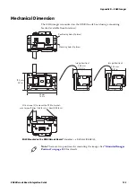
Mechanical Dimension
The EA30 imager is mounted on the ED40 decode board using a mounting
bracket (available from Intermec).
EA30 Mounted on the ED40 Decode Board:
Tolerances = ± 0.20 mm (0.008 in).
Positioning holes (2 places)
Mounting holes (2 places)
19.5 mm
0.77 in
34 mm
1.34 in
M1.6 screws (2) to mount the PCB to bracket:
max torque 19 Ncm (1.68 lb-in) ± 1 Ncm (0.09 lb-in)
20.9 mm
0.82 in
23.2 mm
0.91 in
Imager Position 1
Imager Position 2
Note:
There are two positions for mounting the imager. See
for details.
Содержание ED40
Страница 1: ...Decode Board Used with EA11 EA20X EA21 and EA30 Imagers ED40 Integration Guide EA11 EA20X EA21 EA30 ...
Страница 4: ...iv ED40 Decode Board Integration Guide ...
Страница 22: ...Chapter 2 Mechanical Integration 10 ED40 Decode Board Integration Guide ...
Страница 32: ...Chapter 3 Electrical Integration 20 ED40 Decode Board Integration Guide ...
Страница 41: ...Chapter 4 ED40 Setup ED40 Decode Board Integration Guide 29 UPC A SW 4B 40 01 UPC E SW 4B 41 01 ...
Страница 48: ...Chapter 4 ED40 Setup 36 ED40 Decode Board Integration Guide UPC A ...
Страница 50: ...Chapter 4 ED40 Setup 38 ED40 Decode Board Integration Guide ...
Страница 84: ...Appendix A EA11 Imager 72 ED40 Decode Board Integration Guide Scanning Current EA11 ED40 Scanning Current USB ...
Страница 92: ...Appendix A EA11 Imager 80 ED40 Decode Board Integration Guide ...
Страница 104: ...Appendix B EA20X Imager 92 ED40 Decode Board Integration Guide Scanning Current EA20X ED40 Scanning Current USB ...
Страница 122: ...Appendix C EA21 Imager 110 ED40 Decode Board Integration Guide Scanning Current EA21 ED40 Scanning Current USB ...
Страница 130: ...Appendix C EA21 Imager 118 ED40 Decode Board Integration Guide ...
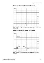
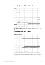
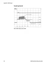
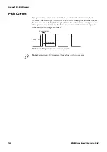
Страница 142: ...Appendix D EA30 Imager 130 ED40 Decode Board Integration Guide Scanning Current EA30 ED40 Scanning Current USB ...
Страница 153: ...Appendix D EA30 Imager ED40 Decode Board Integration Guide 141 ...
Страница 154: ......