


Appendix B — EA20X Imager
ED40 Decode Board Integration Guide
95
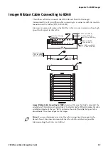
Imager Ribbon Cable Connecting to ED40
The ribbon cable that connects the ED40 decode board to the imager
(unmounted) is a 21-pin ribbon cable connecting to a connector with tin contacts
manufactured by Molex (P/N 54393-2182).
Intermec recommends using a shielded flex cable to contain emission from high
speed clock signals in this cable.
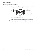
Imager Ribbon Cable Connecting to ED40:
Because of the way the shield is grounded, the
orientation of this cable is not symmetrical. The shield is tied to PIN1 which makes the cable
orientation important. the text “DB1”is printed on the end of the cable that goes to the
decode board. The other end goes to the imager.
0.660 cm ±0.005
(0.260 in ±0.002)
2X
4X 0.762 cm (0.300 in)
4X 0.635 cm (0.250 in)
2X 0.127 cm (0.050 in)
4X R 0.020 cm ±0.010
(0.008 in ±0.004)
5.080 cm
(2.000 in)
0.635 cm
(0.250 in)
0.635 cm
(0.250 in)
Overall thickness
0.020 cm ±0.003
(0.008 in ±0.001)
Vendor Part Marking
Orientation
Note:
If you are designing your own flex cable connecting the imager to the
decode board, Intermec recommends that the cable be as short as possible.
Maximum length is 10.16 cm (4.00 in).
Содержание ED40
Страница 1: ...Decode Board Used with EA11 EA20X EA21 and EA30 Imagers ED40 Integration Guide EA11 EA20X EA21 EA30 ...
Страница 4: ...iv ED40 Decode Board Integration Guide ...
Страница 22: ...Chapter 2 Mechanical Integration 10 ED40 Decode Board Integration Guide ...
Страница 32: ...Chapter 3 Electrical Integration 20 ED40 Decode Board Integration Guide ...
Страница 41: ...Chapter 4 ED40 Setup ED40 Decode Board Integration Guide 29 UPC A SW 4B 40 01 UPC E SW 4B 41 01 ...
Страница 48: ...Chapter 4 ED40 Setup 36 ED40 Decode Board Integration Guide UPC A ...
Страница 50: ...Chapter 4 ED40 Setup 38 ED40 Decode Board Integration Guide ...
Страница 84: ...Appendix A EA11 Imager 72 ED40 Decode Board Integration Guide Scanning Current EA11 ED40 Scanning Current USB ...
Страница 92: ...Appendix A EA11 Imager 80 ED40 Decode Board Integration Guide ...
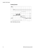
Страница 104: ...Appendix B EA20X Imager 92 ED40 Decode Board Integration Guide Scanning Current EA20X ED40 Scanning Current USB ...
Страница 122: ...Appendix C EA21 Imager 110 ED40 Decode Board Integration Guide Scanning Current EA21 ED40 Scanning Current USB ...
Страница 130: ...Appendix C EA21 Imager 118 ED40 Decode Board Integration Guide ...
Страница 142: ...Appendix D EA30 Imager 130 ED40 Decode Board Integration Guide Scanning Current EA30 ED40 Scanning Current USB ...
Страница 153: ...Appendix D EA30 Imager ED40 Decode Board Integration Guide 141 ...
Страница 154: ......