User’s Manual of NS3550-24T/4S
125
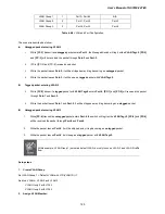
VLAN Group 1
1
Port-7~Port-24
N/A
VLAN Group 2
2
Port-1, Port-2
Port-3
VLAN Group 3
3
Port-4, Port-5
Port-6
Table 4-6-2
VLAN and Port Configuration
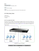
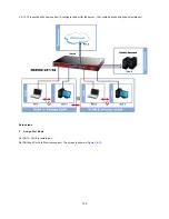
The scenario described as follow:
Untagged packet entering VLAN 2
1.
While
[PC-1]
transmit an
untagged
packet enters
Port-1
, the Managed Switch will tag it with a
VLAN Tag=2
.
[PC-2]
and
[PC-3]
will be received the packet through
Port-2
and
Port-3
.
2.
[PC-4],[PC-5] and [PC-6] received no packet.
3.
While the packet leaves
Port-2
, it will be stripped away it tag becoming an
untagged
packet.
4.
While the packet leaves
Port-3
, it will keep as a
tagged
packet with
VLAN Tag=2
.
Tagged packet entering VLAN 2
5.
While
[PC-3]
transmit a
tagged
packet with
VLAN Tag=2
enters
Port-3
,
[PC-1]
and
[PC-2]
will received the packet
through
Port-1
and
Port-2
.
6.
While the packet leaves
Port-1
and
Port-2
, it will be stripped away it tag becoming an
untagged
packet.
Untagged packet entering VLAN 3
1. While
[PC-4]
transmit an
untagged
packet enters
Port-4
, the switch will tag it with a
VLAN Tag=3
.
[PC-5]
and
[PC-6]
will be received the packet through
Port-5
and
Port-6
.
2.
While the packet leaves
Port-5
, it will be stripped away it tag becoming an
untagged
packet.
3.
While the packet leaves
Port-6
, it will keep as a
tagged
packet with
VLAN Tag=3
.
At this example, VLAN Group 1 just set as default VLAN, but only focus on VLAN 2 and VLAN 3 traffic
flow
Setup steps
1. Create
VLAN
Group
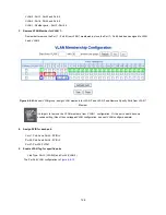
Set VLAN Group 1 = Default-VLAN with VID (VLAN ID) =1
Add two VLANs – VLAN 2 and VLAN 3
VLAN Group 2 with VID=
2
VLAN Group 3 with VID=
3
2. Assign
VLAN
Member:
Содержание IFS NS3550-24T/4S
Страница 1: ...P N 1072569 REV 00 05 ISS 11OCT12 IFS NS3550 24T 4S User Manual ...
Страница 37: ...User s Manual of NS3550 24T 4S 37 ...
Страница 96: ...96 Figure 4 4 6 Port Mirror Configuration Page Screenshot ...
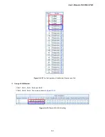
Страница 127: ...User s Manual of NS3550 24T 4S 127 Figure 4 6 10 Port 1 Port 6 VLAN Configuration ...
Страница 151: ...User s Manual of NS3550 24T 4S 151 Figure 4 8 1 Multicast Service Figure 4 8 2 Multicast Flooding ...
Страница 184: ...184 Figure 4 9 14 Voice VLAN Configuration Page Screenshot ...
Страница 204: ...204 Figure 4 11 4 Network Access Server Configuration Page Screenshot ...
Страница 234: ...234 Figure 4 12 1 Port Limit Control Configuration Overview Page Screenshot ...
Страница 250: ...250 Click to undo any changes made locally and revert to previously saved values ...
Страница 297: ...User s Manual of NS3550 24T 4S 297 ...
Страница 388: ...388 Example Show RADIUS statistics SWITCH security aaa statistics ...
Страница 410: ...410 Parameters vid VLAN ID 1 4095 Default Setting disable ...
Страница 441: ...User s Manual of NS3550 24T 4S 441 Example Enable the mirror mode for port 1 4 SWITCH mirror mode 1 4 enable ...


