Intepro systems 06230250 Скачать руководство пользователя страница 18

Page 18

Intepro Systems

www.inteproate.com

[email protected]

PS 9000 3U Series

1.8.4 

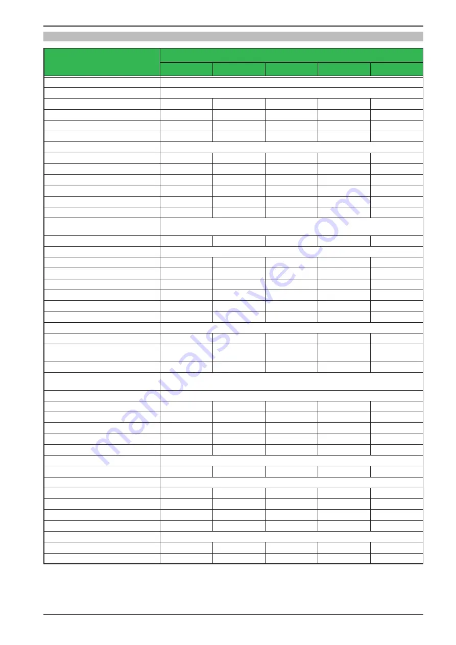
Specific technical data (208 V AC models)

(1 Related to the nominal values, the accuracy defines the maximum deviation between an adjusted values and the true (actual) value.

Example: a 80 V model has min. 0.1% voltage accuracy, that is 80 mV. When adjusting the voltage to 5 V, the actual value is allowed to differ max. 80 mV, which 

means it might be between 4.92 V and 5.08 V.

(2 RMS value: LF 0...300 kHz, PP value: HF 0...20MHz

(3 Typical value at 100% output voltage and 100% power

(4 The display error adds to the error of the related actual value on the DC output

5 kW

Model 208 V

PS 9080-170 PS 9200-70

PS 9360-40

PS 9500-30

PS 9750-20

AC Input

Voltage (L-L)

208 V, ± 10%, 45 - 65 Hz

Input connection

2ph,PE

2ph,PE

2ph,PE

2ph,PE

2ph,PE

Input fuse (internal)

2x T16 A

2x T16 A

2x T16 A

2x T16 A

2x T16 A

Leak current

< 3.5 mA

< 3.5 mA

< 3.5 mA

< 3.5 mA

< 3.5 mA

Power factor

> 0.99

> 0.99

> 0.99

> 0.99

> 0.99

DC Output

Max. output voltage U

Max

80 V

200 V

360 V

500 V

750 V

Max. output current I

Max

170 A

70 A

40 A

30 A

20 A

Max. output power P

Max

5 kW

5 kW

5 kW

5 kW

5 kW

Overvoltage protection range

0...88 V

0...220 V

0...396 V

0...550 V

0...825 V

Overcurrent protection range

0...187 A

0...77 A

0...44 A

0...33 A

0...22 A

Overpower protection range

0…5.5 kW

0…5.5 kW

0…5.5 kW

0…5.5 kW

0…5.5 kW

Temperature coefficient for set 

values Δ/K

Voltage / current: 100 ppm

Output capacitance (approx.)

8500 μF

2500 μF

400 μF

250 μF

100 μF

Voltage regulation

Adjustment range

0...81.6 V

0...204 V

0...367.2 V

0...510 V

0...765 V

Accuracy 

(1 

(at 23±5°C / 73±9°F))

< 0.1% U

Max

< 0.1% U

Max

< 0.1% U

Max

< 0.1% U

Max

< 0.1% U

Max

Line regulation at ±10% ΔU

AC

< 0.02% U

Max

< 0.02% U

Max

< 0.02% U

Max

< 0.02% U

Max

< 0.02% U

Max

Load regulation at 0...100% load

< 0.05% U

Max

< 0.05% U

Max

< 0.05% U

Max

< 0.05% U

Max

< 0.05% U

Max

Rise time 10...90%

Max. 30 ms

Max. 30 ms

Max. 30 ms

Max. 30 ms

Max. 30 ms

Settling time after load step

< 1.5 ms

< 1.5 ms

< 1.5 ms

< 1.5 ms

< 1.5 ms

Display: Resolution

See section 

„1.9.6.4. Resolution of the displayed values“

Display: Accuracy 

(4

≤ 0.2% U

Max

≤ 0.2% U

Max

≤ 0.2% U

Max

≤ 0.2% U

Max

≤ 0.2% U

Max

Ripple 

(2

< 200 mV

PP


< 16 mV

RMS

< 300 mV

PP


< 40 mV

RMS

< 550 mV

PP


< 65 mV

RMS

< 350 mV

PP


< 70 mV

RMS

< 800 mV

PP


< 200 mV

RMS

Remote sensing compensation

Max. 5% U

Max

Max. 5% U

Max

Max. 5% U

Max

Max. 5% U

Max

Max. 5% U

Max

Fall time at no load after switching  

DC output off

Down from 100% to <60 V: less than 10 s

Current regulation

Adjustment range

0...173.4 A

0...71.4 A

0...40.8 A

0...30.6 A

0...20.4 A

Accuracy 

(1 

(at 23±5°C / 73±9°F))

< 0.2% I

Max

< 0.2% I

Max

< 0.2% I

Max

< 0.2% I

Max

< 0.2% I

Max

Line regulation at ±10% ΔU

AC

< 0.05% I

Max

< 0.05% I

Max

< 0.05% I

Max

< 0.05% I

Max

< 0.05% I

Max

Load regulation at 0...100% ΔU

OUT

< 0.15% I

Max

< 0.15% I

Max

< 0.15% I

Max

< 0.15% I

Max

< 0.15% I

Max

Ripple 

(2

< 80 mA

RMS

< 22 mA

RMS

< 5.2 mA

RMS

< 16 mA

RMS

< 16 mA

RMS

Display: Resolution

See section 

„1.9.6.4. Resolution of the displayed values“

Display: Accuracy 

(4

≤ 0.2% I

Max

≤ 0.2% I

Max

≤ 0.2% I

Max

≤ 0.2% I

Max

≤ 0.2% I

Max

Power regulation

Adjustment range 

0…5.1 kW

0…5.1 kW

0…5.1 kW

0…5.1 kW

0…5.1 kW

Accuracy 

(1 

(at 23±5°C / 73±9°F))

< 1% P

Max

< 1% P

Max

< 1% P

Max

< 1% P

Max

< 1% P

Max

Line regulation at ±10% ΔU

AC

< 0.05% P

Max

< 0.05% P

Max

< 0.05% P

Max

< 0.05% P

Max

< 0.05% P

Max

Load reg. at 10-90% ΔU

OUT

 * ΔI

OUT

< 0.75% P

Max

< 0.75% P

Max

< 0.75% P

Max

< 0.75% P

Max

< 0.75% P

Max

Display: Resolution

See section 

„1.9.6.4. Resolution of the displayed values“

Display: Accuracy 

(4

≤ 0.8% P

Max

≤ 0.8% P

Max

≤ 0.8% P

Max

≤ 0.8% P

Max

≤ 0.8% P

Max

Efficiency 

(3

≈ 93%

≈ 95%

≈ 95%

≈ 95,5%

≈ 94%

Содержание 06230250

Страница 1: ...ntion This document is only valid for devices with TFT dis play and firmwares KE 3 07 standard version or KE 2 11 GPIB 3W and HMI 2 03 or higher For availability of up dates for your device check our...

Страница 2: ......

Страница 3: ...supply 38 2 3 5 Connection to DC loads 41 2 3 6 Connection of remote sensing 42 2 3 7 Grounding of the DC output 43 2 3 8 Connecting the Share bus 43 2 3 9 Connecting the analog interface 43 2 3 10 C...

Страница 4: ...es 4 SERVICEAND MAINTENANCE 4 1 Maintenance cleaning 68 4 2 Fault finding diagnosis repair 68 4 2 1 Firmware updates 68 4 3 Calibration readjustment 69 4 3 1 Preface 69 4 3 2 Preparation 69 4 3 3 Cali...

Страница 5: ...91000 40 3U 06230270 PS 9040 340 3U 06230256 PS 9040 510 3U 06230263 PS 91500 30 3U 06230269 1 1 4 Explanation of symbols Warning and safety notices as well as general notices in this document are sho...

Страница 6: ...stead of Ethernet port US208V 208 V model for US market Construction not stated everywhere 3U 19 frame with 3U Maximum current of the device in Ampere Maximum voltage of the device in Volt Series 9 Se...

Страница 7: ...product label Do not insert any object particularly metallic through the ventilator slots Avoid any use of liquids near the equipment Protect the device from wet damp and conden sation For power suppl...

Страница 8: ...operating procedures for the local conditions regularly control that the operating procedures are current update the operating procedures where necessary to reflect changes in regulation standards or...

Страница 9: ...e device and or the load could be damaged Signal OCP OverCurrent Shutdown of the DC output due to excess of the preset limit Non critical protects the load from excessive current consumption Signal OP...

Страница 10: ...UMax 0 1 UMax Line regulation at 10 UAC 0 02 UMax 0 02 UMax 0 02 UMax 0 02 UMax 0 02 UMax Load regulation at 0 100 load 0 05 UMax 0 05 UMax 0 05 UMax 0 05 UMax 0 05 UMax Rise time 10 90 Max 30 ms Max...

Страница 11: ...ure 20 70 C 4 158 F Humidity 80 not condensing Standards EN 61010 1 2010 EMC T V approved acc IEC 61000 6 2 2005 and IEC 61000 6 3 2006 Class B Overvoltage category 2 Protection class 1 Pollution degr...

Страница 12: ...20 mVPP 25 mVRMS 300 mVPP 40 mVRMS Remote sensing compensation Max 5 UMax Max 5 UMax Max 5 UMax Max 5 UMax Max 5 UMax Fall time at no load after switching DC output off Down from 100 to 60 V less than...

Страница 13: ...erature 20 70 C 4 158 F Humidity 80 not condensing Standards EN 61010 1 2010 EMC T V approved acc IEC 61000 6 2 2005 and IEC 61000 6 3 2006 Class B Overvoltage category 2 Protection class 1 Pollution...

Страница 14: ...25 mVRMS Remote sensing compensation Max 5 UMax Max 5 UMax Max 5 UMax Max 5 UMax Max 5 UMax Fall time at no load after switching DC output off Down from 100 to 60 V less than 10 s Current regulation A...

Страница 15: ...ture 20 70 C 4 158 F Humidity 80 not condensing Standards EN 61010 1 2010 EMC T V approved acc IEC 61000 6 2 2005 and IEC 61000 6 3 2006 Class B Overvoltage category 2 Protection class 1 Pollution deg...

Страница 16: ...mVRMS Remote sensing compensation Max 5 UMax Max 5 UMax Max 5 UMax Max 5 UMax Max 5 UMax Fall time at no load after switching DC output off Down from 100 to 60 V less than 10 s Current regulation Adj...

Страница 17: ...e 20 70 C 4 158 F Humidity 80 not condensing Standards EN 61010 1 2010 EMC T V approved acc IEC 61000 6 2 2005 and IEC 61000 6 3 2006 Class B Overvoltage category 2 Protection class 1 Pollution degree...

Страница 18: ...at 23 5 C 73 9 F 0 1 UMax 0 1 UMax 0 1 UMax 0 1 UMax 0 1 UMax Line regulation at 10 UAC 0 02 UMax 0 02 UMax 0 02 UMax 0 02 UMax 0 02 UMax Load regulation at 0 100 load 0 05 UMax 0 05 UMax 0 05 UMax 0...

Страница 19: ...20 70 C 4 158 F Humidity 80 not condensing Standards EN 61010 1 2010 EMC T V approved acc IEC 61000 6 2 2005 and IEC 61000 6 3 2006 Class B Overvoltage category 2 Protection class 1 Pollution degree...

Страница 20: ...RMS 550 mVPP 65 mVRMS 350 mVPP 70 mVRMS 800 mVPP 200 mVRMS Remote sensing compensation Max 5 UMax Max 5 UMax Max 5 UMax Max 5 UMax Max 5 UMax Fall time at no load after switching DC output off Down fr...

Страница 21: ...e 20 70 C 4 158 F Humidity 80 not condensing Standards EN 61010 1 2010 EMC T V approved acc IEC 61000 6 2 2005 and IEC 61000 6 3 2006 Class B Overvoltage category 2 Protection class 1 Pollution degree...

Страница 22: ...PP 25 mVRMS 300 mVPP 40 mVRMS 550 mVPP 65 mVRMS 350 mVPP 70 mVRMS Remote sensing compensation Max 5 UMax Max 5 UMax Max 5 UMax Max 5 UMax Max 5 UMax Fall time at no load after switching DC output off...

Страница 23: ...ature 20 70 C 4 158 F Humidity 80 not condensing Standards EN 61010 1 2010 EMC T V approved acc IEC 61000 6 2 2005 and IEC 61000 6 3 2006 Class B Overvoltage category 2 Protection class 1 Pollution de...

Страница 24: ...P 400 mVRMS Remote sensing compensation Max 5 UMax Max 5 UMax Max 5 UMax Fall time at no load after switching DC output off Down from 100 to 60 V less than 10 s Current regulation Adjustment range 0 6...

Страница 25: ...0 C 4 158 F Humidity 80 not condensing Standards EN 61010 1 2010 EMC T V approved acc IEC 61000 6 2 2005 and IEC 61000 6 3 2006 Class B Overvoltage category 2 Protection class 1 Pollution degree 2 Ope...

Страница 26: ...3U Series A Power switch D Share Bus and remote sensing connection B Control panel E DC output view shows terminal type 1 C Control interfaces digital analog F AC input with plug fixture strain relie...

Страница 27: ...Page 27 Intepro Systems www inteproate com support inteproate com PS 9000 3U Series Figure 3 Left hand side Figure 4 Right hand side...

Страница 28: ...Page 28 Intepro Systems www inteproate com support inteproate com PS 9000 3U Series Figure 5 View from above...

Страница 29: ...the decimal position of a value to be changed cursor 4 Button bank Button Activates the setup menu for various device settings see 3 4 3 Configuration in the setup menu or the mini menu Button Navigat...

Страница 30: ...lated up to 1500 V DC In addition the devices offer as standard the possibility for parallel connection in Share bus operation for constant current sharing Operating in this way allows up to 16 units...

Страница 31: ...vailable POWER RACKS 19 rack Racks in various configurations up to 47U as parallel systems are available also mixed with electronic load devices to create test systems Further information in our produ...

Страница 32: ...usted by rotating the knobs below the display whereas pushing the knobs are used to select the digit to be changed Logically the values are increased by clockwise turning and decreased by anti clock w...

Страница 33: ...ible assignments whereas the right hand knob remains assigned to the set value of current U I U P Left rotary knob voltage Right rotary knob current Left rotary knob voltage Right rotary knob power Th...

Страница 34: ...col or by SCPI language The device recognises the message protocol used automatically If remote control is in operation the USB port has no priority over either the analog interface or the Ethernet in...

Страница 35: ...R ELR 9000 ELR 9000 HP EL 9000 B PSE 9000 PS 9000 1U PS 9000 2U PS 9000 3U From hardware revision 2 see type label in case the label doesn t show Revision on type label it s revision 1 1 9 11 Sense co...

Страница 36: ...y 2 1 3 Storage In case of long term storage of the equipment it is recommended to use the original packaging or similar Storage must be in dry rooms if possible in sealed packaging to avoid corrosion...

Страница 37: ...ed as well as voltage loss which depends on cable length and heating To compensate for these the cable cross section should be increased and the cable length reduced 2 3 3 Installing the device Select...

Страница 38: ...tor is imperative and must always be wired For the selection of a suitable cable cross section the rated AC current of the device and the cable length are decisive Based on the connection of one singl...

Страница 39: ...the sizing of wiring cross section the power of the device and the cable length are decisive The table below gives the maximum output current for each phase Based on the connection of a standalone uni...

Страница 40: ...d current distribution on the three phases See table in 2 3 4 for the max phase currents The 15 kW models are an exception because they already consume balanced current on all three phases they requir...

Страница 41: ...m up to 170 A 70 mm up to 210 A 95 mm up to 340 A 2x70 mm up to 510 A 2x120 mm per connection pole multi conductor insulated openly suspended Single cables of for example 70 mm may be replaced by e g...

Страница 42: ...el of maximum possible compensation is given If that is insufficient the cable cross section must be increased Both pins NC of the Sense connector must not be wired Remote sensing is only effective du...

Страница 43: ...The Share bus is referenced to DC minus When building a series connection where allowed depending on model the DC minus will shift its potential and so will the Share bus 2 3 9 Connecting the analog i...

Страница 44: ...on via the device s website you need the device to be connected to a network or directly to a PC which can access the default IP 192 168 0 2 How to do the network setup on the device website 1 In case...

Страница 45: ...tant voltage operation CV The DC output voltage of a power supply is held constant on the adjusted value unless the output current or the output power according to P UOUT IOUT reaches the adjusted cur...

Страница 46: ...also be read via digital interface 3 2 3 Power regulation constant power power limiting Power regulation also known as power limiting or constant power CP keeps the DC output power of a power supply c...

Страница 47: ...cooling down the device can automatically switch the power stage back on depending on the setting of parameter DC output after OT alarm See section 3 4 3 1 3 3 3 Overvoltage An overvoltage alarm OVP w...

Страница 48: ...can signal undefined statuses on the output pins such as OT or OVP Those signals must be ignored until the device has finished booting and is ready to work 3 4 2 Switching the device off On switch off...

Страница 49: ...ignaling further device alarms 7 possible combinations OVP Enable disable signaling of alarm OVP on pin 14 OCP Enable disable signaling of alarm OCP on pin 14 OPP Enable disable signaling of alarm OPP...

Страница 50: ...ion year month day Save and exit This menu item saves and leaves the setup menu to main display 3 4 3 3 Menu Reset Device Entering this menu item will prompt for acknowledgement to reset the device co...

Страница 51: ...the network address of a domain name server short DNS which has to be present in order to translate the host name to the device s IP so the device could alternatively access by the host name Enable T...

Страница 52: ...or if it should be switched off when no input via push buttons or rotary knob is done for 60 s As soon as input is done the backlight returns automatically Furthermore the backlight intensity can be...

Страница 53: ...375 V As soon as the device is switched to analog remote control it would put out minimum 10V even there is nothing connected to voltage control input VSEL Beyond those limits values given by digital...

Страница 54: ...just output voltage and the right hand knob to adjust the output current In mode UP turn the right hand knob to adjust the output power The arrow buttons can be used to toggle between adjustment of cu...

Страница 55: ...control panel being locked Switching the DC output on during manual operation or digital remote control can be disabled by pin REM SB of the built in analog interface For more information refer to 3...

Страница 56: ...ve Remote then remote control is immediately terminated and must be reactivated at the PC once Local is no longer active If remote control is via the analog interface is active Remote then remote oper...

Страница 57: ...respond to 0 100 nominal values 0 100 actual values correspond to 0 5 V at the actual value outputs CMON VMON 0 10 V Reference voltage 10 V 0 10 V set values VSEL CSEL PSEL correspond to 0 100 nominal...

Страница 58: ...x 1 mA at 5 V ULOW to HIGH typ 3 V Rec d sender Open collector against DGND 6 ALARMS 1 DO Overheating or power fail alarm Alarm HIGH UHigh 4 V No alarm LOW ULow 1 V Quasi open collector with pull up a...

Страница 59: ...the specification of the controlling application Also see pin diagrams above In remote control pin REM SB is used to switch the DC output of the device on and off This func tion is also available wit...

Страница 60: ...ed on or off by pushbutton or digital command LOW Inverted HIGH Inverted DC output will be switched off and locked Later it can be switched on again by toggling the pin During lock pushbutton or digit...

Страница 61: ...itch off the DC output by pulling pin REM SB to the level that corresponds to DC output off switch it on again See section 3 5 4 7 Application examples for levels and logic How to acknowledge an alarm...

Страница 62: ...lteration of a value during manual operation the rotary knobs or the key strip of the control panel HMI can be locked so that no alteration will be accepted without prior unlocking For additional safe...

Страница 63: ...ttings limits and monitoring thresholds quickly without having to readjust these As all HMI settings are saved in the profile including language a profile change can also be accompanied by a change in...

Страница 64: ...very unit in the parallel operation is simply connected to the next unit using cables with cross section according to the maximum current and with short as possible length 3 9 1 2 Wiring the Share bus...

Страница 65: ...h power supply like for example PS PSI 9080 170 3U with PSI 9080 170 3U or PS 9080 170 3U Series connection in Master Slave mode isn t supported It means all units have to controlled separately regard...

Страница 66: ...its for the application should be set in the power supply This can be done via the interface The electronic load should preferably be in operating mode CV The load will then using the Share Bus contro...

Страница 67: ...h event type Alarm to stop discharging at a certain low voltage threshold Assumption battery has a voltage of 26 V at test start DC input s and DC output s of all units switched off In this combinatio...

Страница 68: ...ing a fault description in as much detail as possible is attached if shipping destination is abroad the necessary customs papers are attached 4 2 1 Firmware updates Firmware updates should only be ins...

Страница 69: ...measure the shunt voltage when readjusting the current If the current is also going to be calibrated a suitable DC current shunt ideally specified for at least 1 25 times the max output current of th...

Страница 70: ...e load or sink and start to measure the output current I mon 4 The next screen requests you to enter the output current Measured data measured with the shunt Enter it using the right hand rotary knob...

Страница 71: ...ia Save and exit will discard calibra tion data and the procedure would have to be repeated 5 Contact and support 5 1 Repairs Repairs if not otherwise arranged between supplier and customer will be ca...

Страница 72: ...m Europe Africa Intepro UK Ltd 9 Lakeside Business Park Swan Lane Sandhurst Berkshire GU47 9DN UK Tel 44 012 5287 5600 Asia Oceania Intepro Power Electronics Shenzhen Co Ltd No 828 Block 7 Fourth Indu...

Отзывы: