


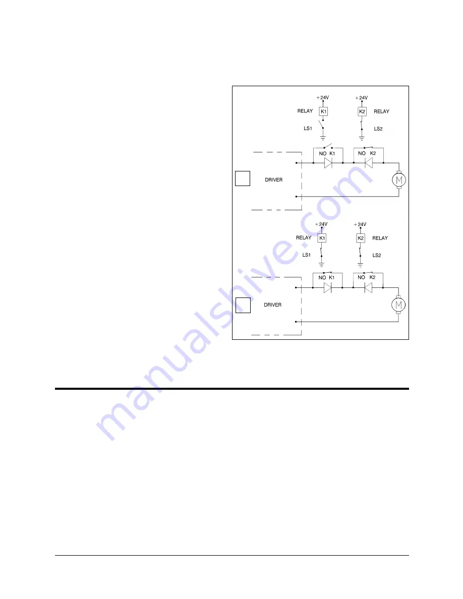
As shown in Figure 7-7A, when limit switch 1 is activated (that is, when the
button is depressed), the relay contact opens and the relay is deenergized. The
motor cannot move the joint
beyond this point. The diode
allows the motor to reverse
direction, thus permitting the
joint to move away from the
limit switch.
When the limit switch is
activated, it causes a control
error, resulting in the activation
of COFF, and an impact
protection message.
CON must be activated and the
robot arm must be manually
moved (using keyboard or teach
pendant) away from the impact
condition.
As long as the axis has not
reached one of its limits, the
relay contact remains closed,
and the diode has no effect on
the circuit, as shown in Figure
7-7B. Current can flow in either
direction; the motor is thus able
to rotate in either direction.
Hard Stops
When the software limits and/or the end of travel switches fail to halt the
movement of the robot arm, it is possible that the momentum of the robot arm
will drive it until it reaches its mechanical limit.
When the joint reaches this hard stop, the impact protection and thermic
protection processes detect an error, thus activating COFF.
CON must be activated and the robot arm must be manually moved away from
the impact condition.
A
B
Figure 7-7: Axis Limit Circuit
User’s Manual
7 - 5
SCORA-ER 14
9603
Содержание SCORA-ER 14
Страница 1: ...SCORA ER 14 User Manual Catalog 100067 Rev B...
Страница 2: ......
Страница 4: ......
Страница 12: ...Figure 2 3 Dimensions Top View Figure 2 4 Working Range Top View SCORA ER 14 2 4 User s Manual 9603...
Страница 36: ...SCORA ER 14 6 12 User s Manual 9603...
Страница 56: ......


