


Gain calibration
•
Enter test gas concentration (value between 30 and 70 % of the measuring range)
•
The current sensor element sensitivity is read with "Read".
•
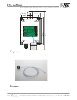
Slide calibration adapter carefully onto the Sensor Cartridge.
•
Apply test gas (flow rate according to the table "calibration", 1 bar ± 10%) to the Sensor Cartridge.
•
When the value is stable, the new gain factor is calculated with "Calibration".
The new gain factor is checked for plausibility and stored in the buffer memory. The current measured value
is output with the new gain factor and the sensor element sensibility is updated.
•
With "Save" the new gain factor is written in the SC memory, only then the gain calibration has been
successfully completed. If you exit the menu without pressing "Save", the original gain data for the
measured value calculation will continue to be used.
By limiting the gain factor, calibration will not be possible anymore when the sensitivity of the sensor
reaches a residual sensitivity of 40 %. Then the Sensor Cartridge has to be replaced
For more information, see the user manual of the
DPT6 EasyConfig Software
.
4.6 Exchange of Sensor Cartridge
Instead of the on-site calibration, the used SC can be easily and conveniently replaced by a calibrated one.
The communication of the local bus (Sensor Cartridge <> BSB) is continuously monitored during
operation and results in an immediate error message on the gas controller in case of fault or
interruption. When replacing the sensor unit, the communication of the local bus is also
interrupted when unplugging the SC connector which leads to an immediate triggering of the
error message.
•
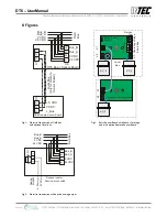
Disconnect the SC connector from the BSB or the RSB (error message will be activated).
•
Loosen the locknut.
•
Remove used SC.
•
Take calibrated SC out of the original packaging, check for gas type, measuring range and valid
calibration date.
•
Insert the SC and retighten with lock nut.
•
Insert the SC plug into the socket at the BSB or RSB. Check plug for proper engagement.
The local bus communication is automatically established and tested. At the same time the gas type and the
measuring range of the "new" SC are compared with the data stored in the BSB. If they match and the
communication is correct, the error message will be automatically acknowledged at the Gas Controller.
The yellow LED of the BSB flashes with a pulse duration of 1 sec., while the SC connector is disconnected
(communication error). After the local bus communication has been re-established and the conformity test
has been successful, the LED will go into flashing mode with 3 sec. pulse duration.
•
Perform functional test of the exchanged SC with gas generator. On successful completion of the
test, the flashing LED goes off after approximately 10 sec.
The sensor element is treated with a defined gas concentration with the help of the gas generator. As a result
the measurement signal acknowledges the LED when an internal switching threshold is reached. With this
test, the complete function chain “Sensor Element > Sensor Cartridge> Local Bus> BSB> Field Bus> GC
Controller” is tested.
INTEC Controls | 12700 Stowe Drive, Suite 100, Poway, CA 92064 | Ph: (858) 578.7887 & (888) GO.INTEC | inteccontrols.com
Specifications subject to change without notice. | GASB2_03_E_0220 | USA 200306 | Page 8 of 15
DT6 – UserManual


