


9 Part Disposal
Since August 2005 there are EC-wide directives defined in the EC Directive 2002/96/EC and in national
codes concerning the waste electrical and electronic equipment also regarding this device.
For private households there are special collecting and recycling possibilities. For this device isn’t registered
for the use in private households, it mustn’t be disposed this way. You can send it back to your national sales
organisation for disposal. If there are any questions concerning disposal, please contact your national sales
organisation.
Outside the EC, you have to consider the corresponding directives.
10 Notes and General Information
It is important to read this user manual thoroughly and clearly in order to understand the information and
instructions. The PolyGard
®
2
devices must be used within product specification capabilities. The appropriate
operating and maintenance instructions and recommendations must be followed.
Due to on-going product development,
INTEC Controls and
MSR-Electronic GmbH reserves the right to
change specifications without notice. The information contained herein is based upon data considered to be
accurate. However, no guarantee is expressed or implied regarding the accuracy of these data.
10.1 Intended Product Application
The PolyGard
®
2 devices are designed and manufactured for control applications and air quality compliance
in commercial buildings and manufacturing plants.
10.2 Installers’ Responsibilities
It is the installer’s responsibility to ensure that all PolyGard
®
2I devices are installed in compliance with all
national and local codes and OSHA requirements. Installation should be implemented only by technicians
familiar with proper installation techniques and with codes, standards and proper safety procedures for
control installations and the latest edition of the National Electrical Code (ANSI/NFPA70).
The equipotential bonding required (also e.g. secondary potential to earth) or grounding measures must be
carried out in accordance with the respective project requirements. It is important to ensure that no ground
loops are formed to avoid unwanted interference in the electronic measuring equipment.
It is also essential to follow strictly all instructions as provided in the user manual.
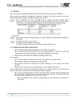
10.3 Maintenance
It is recommended checking the PolyGard
®
2 device regularly. Due to regular maintenance any performance
deviations may easily be corrected. Re-calibration and part replacement in the field may be implemented by
a qualified technician and with the appropriate tools. Alternatively, the easily removable plug-in Sensor
Cartridge with the sensor element may be returned for service to
INTEC Controls
.
10.4 Limited Warranty
INTEC Controls and
MSR-Electronic GmbH warrants the PolyGard
®
2 devices for a period of
two
(
2
) year from
the date of shipment against defects in material or workmanship
; 12 months for sensor elements operating
within normal exposures
. Should any evidence of defects in material or workmanship occur during the
warranty period,
INTEC Controls
will repair or replace the product at their own discretion, without charge.
A
preauthorized RMA number is required for returns.
This warranty does not apply to units that have been altered, had attempted repair, or been subject to abuse,
accidental or otherwise. The warranty also does not apply to units in which the sensor element has been
overexposed or gas poisoned. The above warranty is in lieu of all other express warranties, obligations or
liabilities.
This warranty applies only to the PolyGard
®
2 devices.
INTEC Controls and
MSR-Electronic GmbH shall
not be liable for any incidental or consequential damages arising out of or related to the use o
f the
P
olyGard
®
2 devices.
INTEC Controls | 12700 Stowe Drive, Suite 100, Poway, CA 92064 | Ph: (858) 578.7887 & (888) GO.INTEC | inteccontrols.com
Specifications subject to change without notice. | GASB2_03_E_0220 | USA 200306 | Page 15 of 15
DT6 – UserManual