


3 Electrical Connection
Consider static electricity instructions (ESD)! See point 2.
•
The technical requirements and regulations for wiring, electrical security, as well as project specific
and environmental and local conditions etc. must be observed when mounting.
•
Avoid any influence of external interferences by using shielded cables for the bus line, but do not
connect the shield.
•
When selecting and installing the cables you have to comply with the regulations concerning the
RS-485 bus installation. The installations have to be executed in line topology. Cable length and
type have to be considered as well.
•
Strip the cables as short as possible. It is important to ensure that bare wires, e.g. wire shields do not
come into contact with the mounted PCB (risk of short-circuit).
•
Recommended cable for field bus: J-Y(St)Y 2x2x0.8 LG (20 AWG) min 300V, loop resistance 73
/km
(20.8
/1000 ft).
•
Recommended cable for local bus (remote mounting): J-Y(St)Y 2x2x0.8 LG (20 AWG), min 300 V.
•
Use Copper conductors only if the terminal is only for connection to copper wire.
3.1 Wire Connection
•
Open the cover.
•
Insert the field bus cable from above and connect it.
•
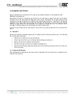
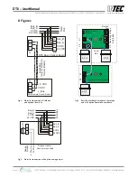
Remove terminal block X4 from BSB, connect cable according to connection diagram fig. 1.
•
Replug terminal carefully on the BSB at X4.
•
For remote sensor:
▪
Insert and connect local bus cable at the basic and remote sensor board.
▪
Remove terminal block X7 at sensor board, connect cable acc. to connection diagram fig. 1.
▪
Replug terminals carefully on both sensor boards.
•
Close cover.
Connecting the 24 V field bus voltage to the local bus terminal X7 can destroy the
DT6
Basic Sensor Board completely!
4 Commissioning
Only trained technicians should perform the following when commissioning:
•
Check for correct mounting location.
•
Check that the
DT6
board is firmly seated in the housing.
•
Check if connection is correct according to connection diagram.
•
Check power voltage.
•
Install the
SC2
Sensor Cartridge(s) if not already installed ex works.
•
Check
SC2
Sensor Cartridge connector for correct engagement.
•
Address the
DT6
Basic Sensor Board (BSB).
•
Register the
SC2
Sensor Cartridge(s) at the
DT6
BSB.
•
Calibrate (if not already factory-calibrated).
Required instruments for commissioning (calibration):
•
Service Tool STL6 or
•
DPT6
incl. EasyConfig
Software
and
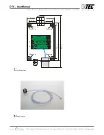
USB/RS-485 communication set:
•
Calibration: See
SC2
user manual.
INTEC Controls | 12700 Stowe Drive, Suite 100, Poway, CA 92064 | Ph: (858) 578.7887 & (888) GO.INTEC | inteccontrols.com
Specifications subject to change without notice. | GASB2_03_E_0220 | USA 200306 | Page 5 of 15
DT6 – UserManual


