


8 Figures
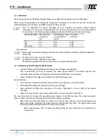
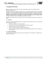
Fig 1: Electrical connection of field bus
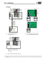
Fig 2 Basic Sensor Board with Sensor Cartridge
and optional local bus
and with option Remote Sensor Board
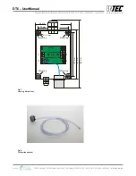
Fig 3: Electrical connection with option analog output
+ 5 VDC
0 VDC
L_Bus
12
3
4
0 VDC
24 VDC
Bus_A
Bus_B
Bus_B
DR6
Remote Sensor Board
Bus_A
X
7
1
2
3
X7
12
3
24 VDC
0 VDC
X4
DT6
Basic Sensor Board
Lo
cal
B
us
(o
nl
y
fo
r R
em
ote
S
en
so
r B
oar
d)
F
iel
d
Bu
s
1
2
3
4
0 VDC
24 VDC
Bus_A
Bus_B
Bus_B
Bus_A
24 VDC
0 VDC
Ana
lo
g
O
ut
put
4 -
20
m
A
0 V
D
C
Fi
el
d
Bu
s
1
2
3
50
0
*
Ω
* Remove resistor,
if device is connected
X2
X2
X7
X7
X3
3
3
21
2
1
Remote Sensor Board
O
pe
rat
in
g
Vo
lta
ge
&
F
iel
d
B
us
Lo
c
al
Bus
SC_2
SC_2
SC_2
X4
2
3
1
4
Basic Sensor
Board
Service
Tool
INTEC Controls | 12700 Stowe Drive, Suite 100, Poway, CA 92064 | Ph: (858) 578.7887 & (888) GO.INTEC | inteccontrols.com
Specifications subject to change without notice. | GASB2_03_E_0220 | USA 200306 | Page 12 of 15
DT6 – UserManual


