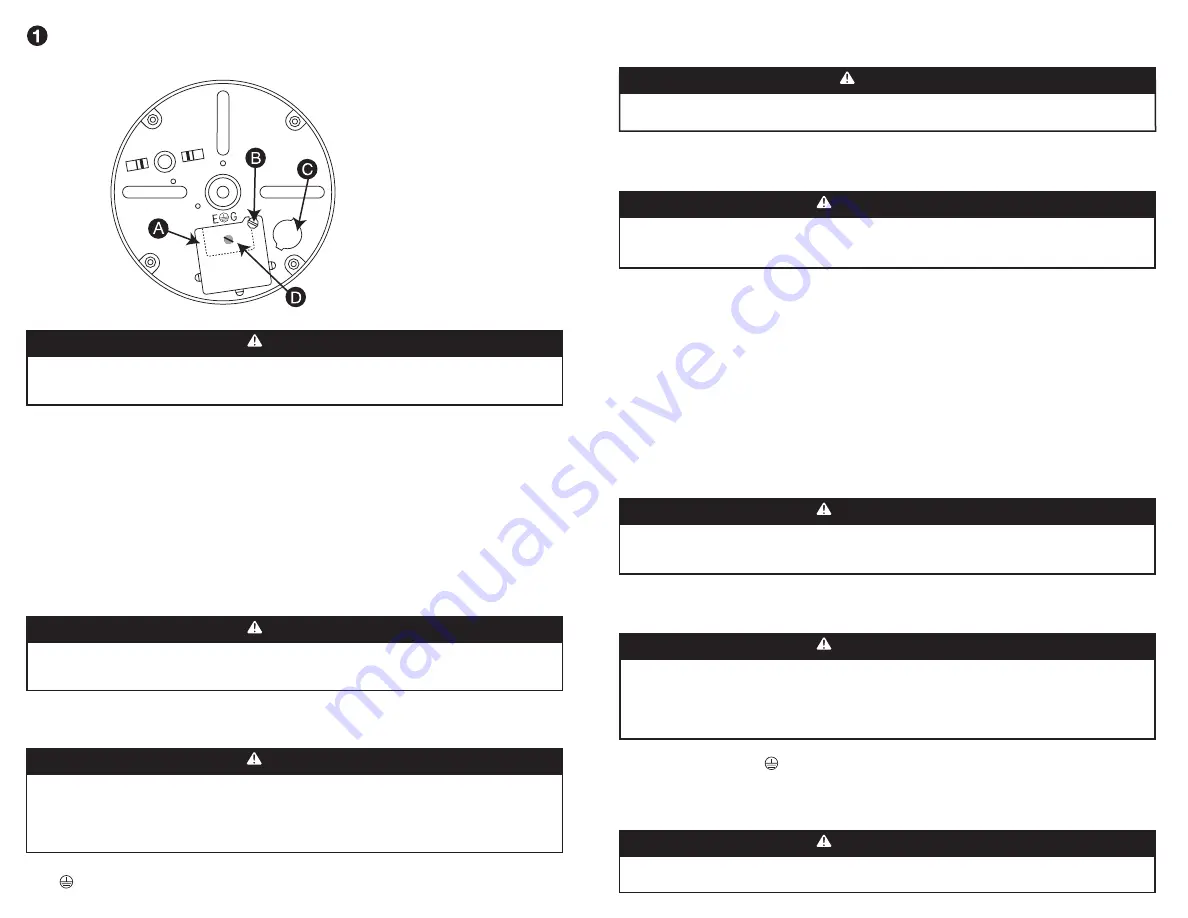
Lower End Frame
Armature D’Extrémité Inférieure
Marco del extremo inferior
A – Terminal Plate
Plaque de borne
Placa terminal
B – Terminal Plate Screw
Vis de plaque de borne
Tornillo de la placa terminal
C – Romex Connector Hole
Orifice de connecteur Romex
Agujero del conector Romex
D – Splice Compartment (green ground
screw is in splice compartment)
Logement du raccord (la vis verte
de mise à la terre se trouve
dans le logement du raccord)
Compartimiento de empalme (el
tornillo de tierra verde está en el
compartimiento de empalme)
1.
Loosen terminal plate screw and remove terminal plate to expose splice compartment located on
bottom of disposer. (Figure 1)
Note: DO NOT remove insulation shield from splice compartment.
2.
Reach in splice compartment and extend the black and white wires.
3.
Keep nut on Romex connector. Tighten nut on Romex connector until nut lays against the connector
shoulder. Screw the Romex connector threaded barrel into the lower end frame and then tighten
Romex connector nut against lower end frame.
4.
Loosen the two screws on the Romex connector and insert the cord. Reach into the splice
compartment and guide the cord into the splice compartment. Make sure the cord is pushed in such
that the Romex connector cord clamp with clamp on the outer insulation encases the cord. Tighten
the two slotted screws until the clamp is tight.
Check to see that a strong pull on the cord
will not cause the cord to slip in the Romex connector.
5.
From the Power Cord Kit, connect the power supply wire with the ribs to the disposer white wire. Connect
the smooth black power cord wire to the disposer black wire. Tighten supplied wire nuts securely and then
wrap with electrical tape.
7.
Place all wires inside the splice compartment.
8.
Replace terminal plate and tighten the terminal plate screw.
6.
Fasten ring terminal on the green ground wire to the green ground screw
(E G) in the splice compartment. Tighten green ground screw securely.
WARNING
ELECTRICAL SHOCK
Turn off electrical power at fuse box or circuit breaker before assembling.
Do not plug unit to power supply until properly completing all assembly steps.
WARNING
ELECTRICAL SHOCK
When securing wire connections with the wire nuts, check to insure that all wire strands are enclosed by the
wire nuts before wrapping connection with electrical tape.
1.
Desserrez la vis de la plaque de borne et retirez-la pour exposer le logement du raccord situé à la
base du broyeur. (Figure 1)
Remarque : NE retirez PAS l‘écran d’isolation du logement du raccord.
2.
Accédez au logement du raccord et allongez les fils noir et blanc.
3.
Laissez l’écrou sur le connecteur Romex. Serrez l’écrou sur le connecteur Romex jusqu’à ce qu’il
repose contre l’épaulement du connecteur. Vissez le barillet fileté du connecteur Romex dans
l’armature inférieure et serrez l’écrou du connecteur Romex contre l’armature inférieure.
4.
Desserrez les deux vis se trouvantsur le connecteur Romex et insérez le cordon. Accédez au
logement du raccord et guidez le cordon dans le logement. Assurez-vous de pousser le cordon de
sorte que le collier de cordon du connecteur Romex soit fixé avec le collier se trouvant sur l’isolant
extérieur entourant le cordon. Serrez les deux vis fendues jusqu’à ce que le collier soit solidement
fixé.
Pour vérifier s’il est solidement fixé, tirez fermement sur le cordon; celui-ci
nedoit pas glisser dans le connecteur Romex.
5.
Du cordon d’alimentation, branchez le fil d’alimentation électrique torsadé au fil blanc du broyeur
de déchets. Branchez le fil noir lisse du cordon au fil noir du broyeur. Serrez solidement les
serre-fils fournis et entourez-les de ruban isolant.
6.
Fixez la borne de l’anneau située sur le fil vert de mise à la terre à la vis verte
de mise à la terre (E G), dans le logement du raccord. Serrez solidement la vis
verte de mise à la terre.
7.
Insérez tous les fils dans le logement du raccord.
8.
Replacez la plaque de borne et serrez-la au moyen de la vis de plaque.
AVERTISSEMENT
CHOC ÉLECTRIQUE
Arrêtez le courant électrique à la boîte ou au disjoncteur de fusible avant de se réunir. Ne branchez pas l’unité
à la source d’alimentation tant que vous n’avez pas exécuté correctement toutes les étapes d’assemblage.
CHOC ÉLECTRIQUE
Lorsque vous fixez les raccordements à l’aide des serre-fils, assurez-vous que toules torons métalliques sont
entourés par serre-fils avant d’envelopper le raccordement dans le ruban isolant.
WARNING
ELECTRICAL SHOCK
DO NOT pinch wires with the terminal plate.
CHOC ÉLECTRIQUE
Ne pincez pas les fils avec le plat terminal.
WARNING
ELECTRICAL SHOCK
Improper connection of the equipment grounding conductor can result in a risk of electrical shock. If you are
in doubt as to whether the appliance is properly grounded, check with a qualified electrician. DO NOT modify
the plug provided with the cord – if it will not fit the receptacle, have a proper receptacle installed by a
qualified electrician. DO NOT use an extension cord.
AVERTISSEMENT
CHOC ÉLECTRIQUE
Un branchement inadéquat au conducteur de mise à la terre d’équipement peut entraîner des risques de choc
électrique. En cas de doute sur lamise à la terre de l’appareil, demandez l’avis d’un électricien qualifié. Ne
modifiez PAS la fiche fournie avec le cordon. Si elle ne s’adapte pas à la prise, faites poser une prise adéquate
par un électricien qualifié. N’utilisez PAS de cordon da rallonge.
AVERTISSEMENT
AVERTISSEMENT


