32
CPS 220/64/SV
Montage- und Betriebsanleitung
CPS 220/64/SV
Mounting and Operating Instructions
32
Bei Netzausfall am Hauptverteiler der Sicherheitsbeleuch-
tung werden alle Verbraucher in Batteriebetrieb geschal-
tet.
An jeden Stromkreis mit Einzelleuchtenüberwachung
können maximal 20 Leuchten angeschlossen werden.
Anschlussklemmen für jeden Stromkreis (L, N, PE) stehen
auf der Klemmleiste X3 zur Verfügung.
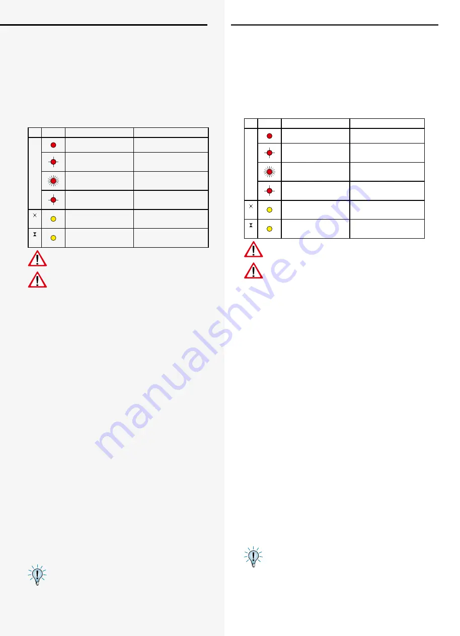
Die LEDs auf den Umschaltungen geben folgende Infor-
mation:
LEDs
Meldung
F
rot (Dauerleuchten) Leuchtenstörung
rot (3 Sek. blinken
1 LED)
Stromkreis hat Über-
last
rot (0,5 Sek. blitzen) keine Ausgangsspan-
nung im Jokerbetrieb
rot (blinken 4 LEDs
schnell)
Busstörung
gelb
Bereitschaftslicht
eingeschaltet
gelb
Dauerlicht eingeschal-
tet
Der maximale Einschaltstrom pro Stromkreis darf
nicht mehr als 250A für 500µs betragen!
Für die Stromkreisumschaltungen nur Orginalsi-
cherungen mit Löschmitteln verwenden.
CP 4x2A 3,15A (Best.Nr. 080 033)
CP 2x4A 6,3A (Best.Nr. 080 026)
CP 1x6A 10A (Best.Nr. 080 019)
jeweiliges Abschaltvermögen 1500A
Die Endstromkreise werden, abhängig von der verwende-
ten Stromkreisumschaltung, wie folgt angeschlossen:
CP 4x2A:
Anschlussklemmen der Endstromkreise: x.1 /
x.2 / x.3 / x.4
CP 2x4A:
Anschlussklemmen der Endstromkreise: x.1 / x.2
Die Klemmen x.3 / x.4 haben keine Funktion!
CP 1x6A:
Anschluss des Endstromkreises an x.1.
Die Klemmen x.2 / x.3 / x.4 haben keine Funktion!
(x = Einschubnr. – z.B. 4.1 = Einschub 4, Stromkreis 1)
6.3.2.10. Stromkreisumschaltungen CP 2x2,5A / 24V
Dieser Typ Stromkreisumschaltung kann in den Anlagen
CPS 220 / 20 und CPS 220 / 64 für INOTEC-Notleuchten
mit 24V-Technik bzw. 24V D.E.R.-Technik eingesetzt
werden. Dazu liefert der Stromkreiseinschub an den
Ausgangsklemmen eine entsprechende Schutzkleinspan-
nung.
Notleuchten mit 24V Technik und 24V D.E.R. Technik
können gemischt an einem Stromkreis betrieben werden.
Jeder 24V D.E.R. Leuchte können bis zu maximal 8 Schalt-
eingänge zugewiesen werden.
Hierbei ist zu beachten, dass der Schalteingang 1
die niedrigste, der Schalteingang 8 die höchste
Priorität hat.
If the power to the main distribution board of the safety
lighting fails, all consumers will be switched to battery
operation.
Up to 20 luminaires can be connected to each circuit with
individual luminaire monitoring. Terminals for each circuit
(L, N, PE) are available on terminal rail X3.
The LEDs on the change-over devices provide the fol-
lowing information:
LEDs
Message
F
Red (steady)
Light fault
Red (3 sec. flashing
1 LED)
Circuit overloaded
Red (0.5 sec flas-
hing)
No output voltage in
joker operation
Red (4 LEDs flashing
quickly)
Bus fault
Yellow
Non-maintained ligh-
ting on
Yellow
Maintained lighting
on
The maximum inrush current per circuit must not
exceed 250A for 500 µs!
Use only original fuses with extinguishing agents
for the change-over devices.
CP 4x2 A
3.15 A (Order no. 080 033)
CP 2x4 A
6.3 A (Order no. 080 026)
CP 1x6 A
10 A (Order no. 080 019)
Breaking capacity in each case 1500 A
Depending on the change-over device used, the final
circuits are connected as follows:
CP 4x2 A:
Terminals on the final circuits: x.1/x.2/x.3/x.4
CP 2x4 A:
Terminals on the final circuits: x.1/x.2
The terminals x.3/x.4 have no function!
CP 1x6 A:
Connection of the final circuit to x.1.
The terminals x.2/x.3/x.4 have no function!
(x = change-over device no. – e.g. 4.1 = change-over
device 4, circuit 1)
6.3.2.10. Change-over devices CP 2x2.5A / 24V
This type of change-over device can be used in systems
CPS 220 / 20 and CPS 220 / 64 for INOTEC-emergency
lights in the 24V or 24V D.E.R. versions. The circuit rack-
mount unit also provides a corresponding safety extra-
low voltage at the output terminals.
24V emergency luminaires and 24V D.E.R. luminaires
can be operated in one circuit at the same time. Up to
8 switching inputs can be allocated to every 24V D.E.R.
luminaire.
Switch input no. 1 has the lowest priority, switch
input no. 8 has the highest priority.
Содержание CPS 220/20
Страница 2: ......
Страница 47: ...47 CPS 220 64 SV Montage und Betriebsanleitung CPS 220 64 SV Mounting and Operating Instructions BCS BCS...
Страница 107: ......


