CLS FUSION
Montage- und Betriebsanleitung
CLS FUSION
Mounting and Operating Instructions
13
6. Mounting
When installing the device you have to consider
the suffi cient load capacity of the according
installation wall as well as the suitable installation
material (dowel). The distance to close compo-
nents, walls or cable channels must be at least 5cm. Oth-
erwise it can have a negative impact on the ventilation.
This can cause an increase in battery temperature and a
reduced lifetime.
The installation distance must be accordingly at
all time. The guarantee claim expires when not
following the rule.
The emergency supply unit CLS FUSION gets
delivered with no batteries installed.
6.1. Device
CLS FUSION - 7Ah
After unpacking the box, lay the device
down and remove the screw at the front
side of the casing. You will now be able
to remove the front part of the casing.
Attach the connected earth wire by plug-
ging it into the rear wall of the casing.
The dimensions for the drill holes
can be taken from the dimen-
sional drawings of the technical
data!
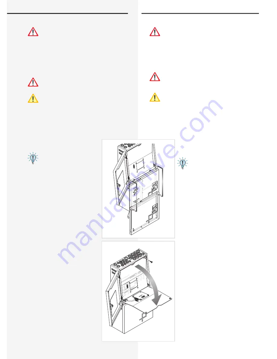
CLS FUSION - 12/24Ah
Open the front door with a control
cabinet key. The earth wire connection
is at the back and can be attached by
plugging. After opening the front door
it is possible to open the battery case.
Push the lower battery protetion a bit
higher and remove it. The battery case is
now open. The earth wire of the battery
case can be attached by plugging and
is located at the back as well. Hook the
battery case into a lower hole and remove
it for the moment. The lower keyhole
suspensions are now visible. To reach the
upper keyhole suspensions, the 10 safety
screw (1) needs to be unscrewed in the
upper right corner of the front plate. Fold
the front plate to the front (2) to see the
electronic parts. Above the terminal strip
there are keyhole suspensions for the wall
mounting. You can fi nd the drill distance
for the installation of the unit in the short
guide and the drawings of the technical
data. After installing the mounting screw
you can now hook the CLS FUSION into
it and tighten the mounting bolts in the
keyhole suspensions.
Note 5. Technical data - Seite 10
6. Montage
Bei der Montage des Gerätes ist auf ausreichende
Tragfähigkeit der entsprechenden Montagewand
sowie auf geeignetes Montagematerial (Dübel) zu
achten. Der seitliche Abstand zu benachbarten
Bauteilen, Wänden oder beispielsweise Kabelkanälen
muss min. 5cm betragen, da sonst die Lüftung stark bee-
infl usst wird. Die Folgen aus der schlechten Belüftung
wäre eine Erhöhung der Batterietemperatur und somit
eine Verkürzung der Lebensdauer.
Der Montageabstand muss eingehalten werden,
andernfalls erlischt der Gewährleistungsanspruch.
Das Notlichtversorgungsgerät CLS FUSION wird
ohne eingebaute Batterien geliefert.
6.1. Gerät
CLS FUSION - 7Ah
Nach dem Auspacken entfernen Sie im liegenden
Zustand die vordere Schraube am Gehäuse. Jetzt kann
die Haube des Gehäu-ses abgenommen werden. Die
angeschlos-sene Erdungsleitung ist steckbar auf der
Gehäuserückwand befestigt.
Die Maßangaben der Bohrlöcher
können den Maßbildern der
technischen Daten entnommen
werden!
CLS FUSION - 12/24Ah
Öff nen Sie die Fronttür mit einem
Schaltschrankschlüssel. Der Erdan-
schluss ist auf der Rückseite und ist
steckbar. Nach dem Öff nen der Fronttür
ist es möglich, das Batteriefach zu
öff nen. Schieben Sie die untere Bat-
terieabdeckung ein kleines Stück
nach oben und ziehen Sie diese ab.
Das Batteriefach ist nun geöff net. Der
Erdanschluss der Batterieabdeckung
ist steckbar und befi ndet sich ebenfalls
auf der Rückseite. Haken Sie die Bat-
terieabdeckung ein Loch tiefer wieder
ein oder entfernen Sie diese vorerst. Die
unteren Schlüssellochaufhängungen
sind jetzt erkennbar. Um an die oberen
Schlüssellochaufhängungen zu gelangen,
muss die 10er Sicherheitstorxschraube
(1) in der rechten oberen Ecke der Front-
abdeckung heraus geschraubt werden.
Klappen Sie nach dem Herausschrauben
die Frontabdeckung nach vorne (2),
sodass der Elektronikteil sichtbar wird.
Über der Klemmleiste befi nden sich die
beiden Schlüssellochaufhängungen für
die Wandmontage. In der mitgelieferten
Kurzanleitung und in den Maßbildern
der technischen Daten können Sie die
Bohrabstände für die Befestigung der
Anlage entnehmen. Nach dem Anbringen
geeigneter Befestigungsschrauben haken
1.
2.


