background image

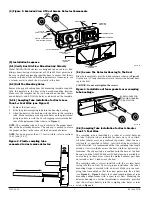
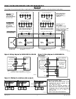
ALARM SIGNAL (+)

AUX POWER (–)

15

20

(+)

(–)

DUCT DETECTOR

DH100ACDCI

PA400 (OPTIONAL)

AUDIBLE ALERT

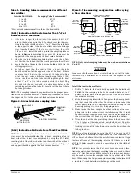
ALARM SIGNAL (+)

AUX POWER (–)

15

20

(+)

(–)

DUCT DETECTOR

DH100ACDCI

RA400Z (OPTIONAL)

REMOTE (LED)

ANNUNCIATOR

RED

ACCESSORY CURRENT LOADS AT 24 VDC
DEVICE
APA451
PA400
RA400Z
RTS451/RTS451KEY
SSK451

STANDBY
12.5mA Max.
0mA
0mA
12mA*
5mA Max.

ALARM
30mA Max.
15mA Max.
10mA Max.
7.5mA Max.
30mA Max.

*NOTE: When a unit is powered at the 120VAC or 220/240VAC input, any

combination of accessories may be used such that the given accessory loads are:

60 mA or less in the standby state;   110 mA or less in the alarm state.

TROUBLE
n/a
n/a
n/a
n/a
9mA Max.

D100-68-00 

I56-1684-007R

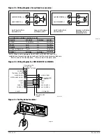
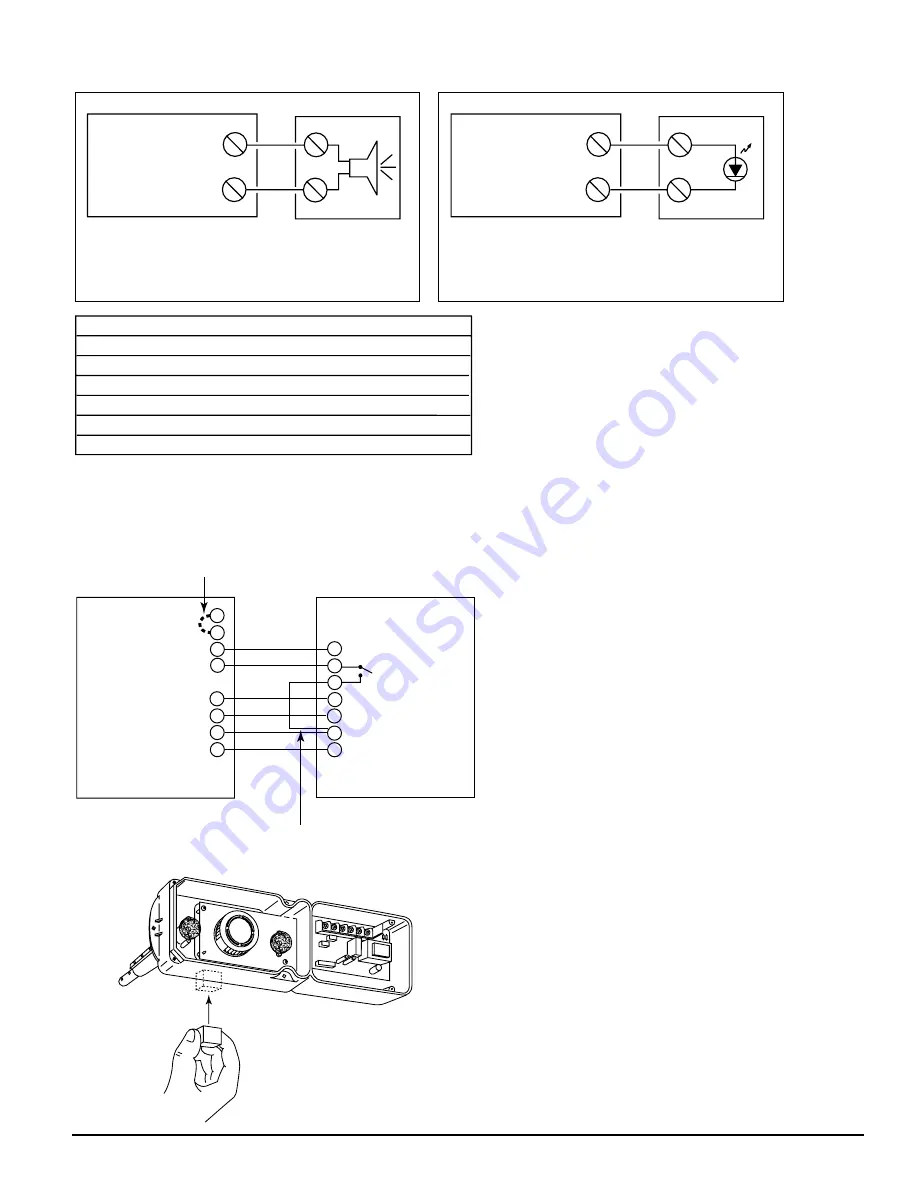
Figure 11. Wiring diagrams for optional accessories:

H0402-01

15 

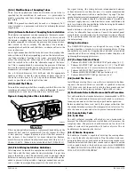
ALARM SIGNAL

 3
14
 2 

RESET

11 

TEST

20 

AUX. POWER (-)

19 

AUX. POWER (+)

SSK451

FIELD INSTALLED

JUMPER FOR

TEMPORAL PATTERN

SUPERVISORY

CONTACT

NO

FIELD INSTALLED

JUMPER

DH100ACDCI

COMMON      3

TEMPORAL SELECT      2

ALARM SIGNAL      1

SUPERVISORY SIGNAL      4

RESET      7

TEST      8

POWER (-)      6

POWER (+)      5

Figure 12. Wiring diagram for  DH100ACDCI to SSK451:

H0403-00

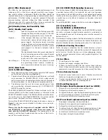
Figure 13. Testing detector alarm:

H0404-00

Содержание DH100ACDCI

Страница 1: ...hut down These detectors are not designed for 2 wire applications For testing the alarm can be enabled by a magnet activated test switch or by the optional remote test station The duct smoke detector latches into alarm state when an alarm occurs A green LED flashes to indicate power a red LED signals local alarm indication and optional accessories offer a variety of annuncia tion capabilities The ...

Страница 2: ...les as indi cated in Figure 4 D100 68 00 2 I56 1684 007R 4 Figure 1 Exploded View Of Duct Smoke Detector Components FOAM GASKETS PLASTIC SAMPLING TUBE CONDUIT HOLES DETECTOR HOUSING TERMINAL STRIP DETECTOR COVER SAMPLING TUBE FILTERS PLASTIC SAMPLING TUBE SELF TAPPING SCREW POWER BOARD DETECTOR BOARD COVER MOUNTING SCREWS H0401 00 H0110 00 5 Installation Sequence 5 1 Verify Duct Air Flow Direction...

Страница 3: ...t the end opposite the duct smoke detector Figure 5 Tube mounting configurations with varying air flow direction AIR FLOW DIRECTION DETECTOR HOUSING DOTS INDICATE POSITION OF SAMPLING TUBE HOLES AIR FLOW DIRECTION DETECTOR HOUSING SAMPLING TUBE EXHAUST TUBE AIR FLOW DIRECTION EXHAUST TUBE SAMPLING TUBE SAMPLING TUBE EXHAUST TUBE DETECTOR HOUSING AIR FLOW DIRECTION DETECTOR HOUSING A B C D HORIZONT...

Страница 4: ... between interconnected detectors or from detectors to auxiliary devices it is usually recommended that single conductor wire be no smaller than 18 gauge The duct smoke detector terminals accommodate wire sizes up to 12 gauge The last foot of conduit should be flexible conduit available in electrical supply houses which facilitates easier installation and puts less strain on the conduit holes in t...

Страница 5: ... RTS451KEY is not required when these accessories are used with the DH100ACDCI detectors The functionality of the magnetic coil has been designed into the circuitry of the new In novair duct smoke detectors 6 2 2 3 SSK451 Multi Signaling Accessory The System Sensor SSK451 Multi Signaling accessory combines a sounder feature with a key activated test and reset function Green amber and red LEDs prov...

Страница 6: ...S ACCEPT 24 VDC 24 VAC 50 60 HZ 120 VAC 50 60 HZ OR 220 240 VAC 50 60 HZ CONNECT POWER SOURCE TO APPROPRIATE TERMINALS OF EACH DETECTOR AUX CONTACT RATINGS 10A 30 VDC RESISTIVE 10A 250 VAC 100mA MINIMUM 5 VDC 1 4 HP 240 VAC 1 8 HP 120 VAC NOT INTENDED FOR CONNECTION TO CONTROL PANELS TROUBLE CONTACT RATING 2 0 A 30 VDC resistive 2 0 A 125 VAC resistive 120 VAC CAUTION Do not loop wire under termin...

Страница 7: ...ination of accessories may be used such that the given accessory loads are 60 mA or less in the standby state 110 mA or less in the alarm state TROUBLE n a n a n a n a 9mA Max D100 68 00 7 I56 1684 007R Figure 11 Wiring diagrams for optional accessories H0402 01 15 ALARM SIGNAL 3 14 2 RESET 11 TEST 20 AUX POWER 19 AUX POWER SSK451 FIELD INSTALLED JUMPER FOR TEMPORAL PATTERN SUPERVISORY CONTACT NO ...

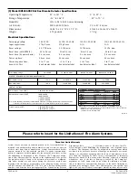
Страница 8: ...60 Hz CURRENT REQUIREMENTS USING NO ACCESSORIES Max standby current 15 mA 35 mA RMS 25 mA RMS 15 mA RMS Max alarm current 70 mA 125 mA RMS 35 mA RMS 25 mA RMS CONTACT RATINGS Alarm initiation contacts SPST 2 0A 30 VDC resistive Alarm auxiliary contacts DPDT 10A 30 VDC 10A 250 VAC 1 4 HP 240 VAC 1 8 HP 120 VAC Trouble contacts SPDT 2 0A 30 VDC resistive 2 0A 125 VAC resistive Note Alarm auxiliary c...

Отзывы: