6
Introduction
Installation and Programming manual
1.2
The system parts and definitions
Power supply module:
a module, connected to the mains 230 Vac, which supplies a stabilized voltage @
24 V (27.6 V) to the system and the charge source to the batteries. The power-supply module is located
below the mother board and is EN54-4 compliant. The mains voltage (230 Vac) is the primary power
source of the system. See also paragraph
7.5 Connecting the Mains
.
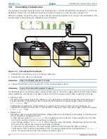
Batteries:
the secondary power source of the system. The power supply station enclosure houses two lead
batteries @ 12V 7Ah (depending on the model) connected in series. The system monitors the battery
status (efficiency and charge). A fault signal will be generated when voltage overload/underload or
inefficient battery conditions occur (Appendix A2). In the event of primary power (230 Vac) failure, the
batteries will take over, however, they will shutdown automatically if the blackout persists. The automatic
battery shutdown feature prevents irreparable damage to the batteries. See also paragraph
7.6 Connecting
the batteries
.
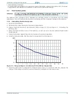
Thermal probe:
an accessory tool connected to the panel and attached to the battery pack. This device
monitors the temperature of the battery pack and regulates the battery charge accordingly. See also
paragraph
7.7 The thermal probe
.
RS485 BUS:
4 wire BUS which allows the power supply station to be connected directly to INIM fire
detection panels (SmartLoop, SmartLight and SmartLine). Four pole shielded-twisted cable must be used
for all connections. See also paragraph
7.2 RS485 BUS wiring
.
1.3
The SmartLevel power supply stations
Product models:
• SPS24040 - Power-supply unit with internal 1.4A @ 27.6V switching power-supply module and housing
for 7Ah, 12V batteries
• SPS24140 - Power-supply unit with internal 4A @ 27.6V switching power-supply module and housing for
17Ah, 12V batteries


