Installation and Programming manual
Installation instructions
19
7.3
Connecting the output channels
Outputs OUT1-2-3 supply 24V (27.6V) and a maximum current of 0.8A for the SPS24040 model and 2.8A
for the SPS24140 model. These outputs can be used to power external devices.
These outputs can be managed via inputs B1, B2, B3 or via the RS485 BUS of an INIM fire-dectection panel
(refer to paragraph
4.1 Controlling the Outputs
).
Use NON-shielded cable. The wire section should be compatible with the wire length and load connected to
the output.
7.4
Connecting the FAULT output
The FAULT output provides a voltage-free terminal which switches 1A 30V loads. The relay is energized
during standby status and closes its common contact to NC. During fault events, the NC contact opens and
the common contact closes to NO. The common contact closes to NC only when all fault conditions clear or
when the PROG jumper is inserted.
7.5
Connecting the Mains
The power-supply module (located under the motherboard) provides the power source to the entire system
and recharges the batteries.
The power-supply module must be connected to a separate line on the electrical switch board. The line
must be protected by a fire-code compliant circuit breaker.
The earthing system must be compliant with the local safety laws in force.
7.5.1
Technical specifications
• Primary power source: 230 V ac (-15% + 10%) 50/60 Hz
• Maximum current draw: 0.5 A for the SPS24040 and 0.9 A for the SPS24140
7.5.2
Wiring
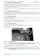
Figure 11 - Connecting the Mains
Danger:
Ensure that the Mains power is switched OFF before starting this procedure.
1. Connect the wires to the power-supply terminal board [A].
2. Using a plastic cable tie, bunch the wires together and attach them firmly to the cable hook [B] on the
backbox.
Attention:
Wiring circuits must not be commingled without proper separation. Adhere to the connection
wiring in the diagram.
A
B


