MAINTENANCE
20
UP6RD–5–175, UP6RM–5–175, UP6RD–5–175
OIL CHANGE PROCEDURE
1. Remove the oil drain plug and allow the oil to drain into a suitable
container.
2. Replace the oil drain plug.
3. Follow the filling procedures in INSTALLATION / HANDLING
section.
BELT CHECKING AND ADJUSTMENT PROCEDURE
Check belt tension occasionally, especially if looseness is
suspected. A quick check to determine if adjustment is proper may be
made by observing the slack side of the belt for a slight bow when the
unit is in operation. If a slight bow is evident, the belt is usually adjusted
satisfactorily.
On enclosed compressors, a belt tension measurement device can
be used to determine the tension of the belt. A belt inspection opening
is provided at the top of the blower housing.
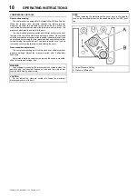
Belt tensioning can be achieved by loosening the motor anchor
screws, pushing the motor away from the pump, and retightening the
motor anchor screws. The motor can be easily moved by placing a
prying tool beneath it. A commercially available spreader or other belt
tensioning device can also be helpful should tensioning be necessary.
On enclosed compressors, a belt tensioning bolt is provided to aid
in moving the motor.
Follow the procedures outlined below to correctly set and measure belt
tension.
1. Lay a straight edge across the top outer surface of the belt drive
from pulley to sheave.
2. At the center of the span, perpendicular to the belt, apply pressure
to the outer surface of the belt with a tension gauge. Force the belt to
the deflection indicated in the table below, and compare the reading on
the tension gauge to the figures shown.
Deflection in Inches
Min Tension (Lbs.)
Max. Tension (Lbs.)
0.17
3.0
6.0
Ensure the pulley and sheave are properly aligned and the motor
anchor screws are adequately retightened prior to restarting the
compressor.
CAUTION
Improper pulley/sheave alignment and belt tension can result in
motor overload, excessive vibration, and premature belt and/or bearing
failure.
To prevent these problems from occurring, ensure the pulley and
sheave are aligned and belt tension is satisfactory after installing new
belts or tensioning existing belts.
FILTER REPLACEMENT
1. Unscrew and remove the wing nut securing the filter housing to its
base.
2. Remove the filter housing and withdraw the old filter element.
3. Install a new filter element and replace the housing, securing it in
place with the wing nut.
ELECTRIC DRAIN VALVE
PRODUCT DESCRIPTION
The Electric Drain Valve removes condensed water and oil from the air
receiver tank. Additional drains may be installed throughout your
compressed air system, including aftercoolers, filters, drip legs and
dryers.
The Electric Drain Valve operates on a timer which can be set to
automatically drain the air receiver tank at operator–determined
intervals.
Key features include:
•
100% continuous duty
•
NEMA 4 enclosure
•
Adjustable time on (0.5 – 10 seconds)
•
Adjustable time off (0.5 – 45 minutes)
•
Stainless steel operator
•
LED to indicate electrical power is on
•
LED to indicate valve is open
•
Manual override
OPERATION
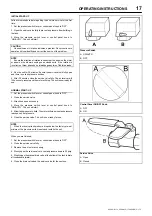
1. Open the strainer ball valve.
Strainer Ball Valve.
OPEN
CLOSED
2. Set the “time off” and “time on” knobs. See TIMER SETTINGS
(below) for an explanation of the settings.
3. During compressor operation, check for air leaks.
TIMER SETTINGS
The “time off” setting determines the interval between cycles from 30
seconds to 45 minutes. The “time on” setting determines the actual time
the compressor drains condensate.
The timer’s cycle rate and drain opening time should be adjusted to
open just long enough to discharge the condensate. The timer is
properly set when it opens and discharges condensate and then vents
air for approximately one second before closing. Adjustments may be
made depending on many factors, including humidity and duty cycle.
TROUBLESHOOTING
TROUBLE
CAUSE
ACTION
Valve will not
close.
1. Debris in solenoid
valve prevents dia-
phragm from seating.
1. Remove solenoid
valve, disassemble,
clean and reassemble
.
2. Short in electrical
component.
2. Check and replace
power cord or timer as
needed.
Timer will not
activate
1. No electrical supply.
1. Apply power.
activate
2. Timer malfunction
2. Replace timer.
3. Clogged port.
3. Clean valve.
4 Solenoid valve
malfunction.
4. Replace solenoid
valve.
5. Clogged strainer.
5. Clean strainer.
Содержание UP6RD-5-175
Страница 2: ......

