Ingersoll-Rand S9V2B040D3PSBA Скачать руководство пользователя страница 22

22

18-CE01D1-1F-EN

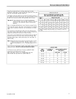
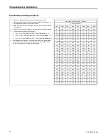
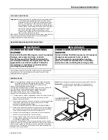
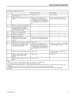
Combustion and Input Check

1.

Make sure all gas appliances are off except the furnace.

2.

Clock the gas meter with the furnace operating (determine the
dial rating of the meter) for one revolution.
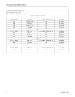
3.

Match the "Sec" column in the gas flow (in cfh) the table with the
time clocked.

4.

Read the "Flow" column opposite the number of seconds clocked.

5.

Use the following factors if necessary:

a.

For 1 Cu. Ft. Dial Gas Flow CFH = Chart Flow Reading ÷ 2

b.

For 1/2 Cu Ft. Dial Gas Flow CFH = Chart Flow Reading ÷ 4

c.

For 5 Cu. Ft. Dial Gas Flow CFH = 10X Chart Flow Reading ÷ 4

6.

Multiply the final figure by the heating value of the gas obtained
from the utility company and compare to the nameplate rating.
This must not exceed the nameplate rating.

Gas Flow in Cubic Feet Per Minute

2 Cubic Foot Dial

Sec.

Flow

Sec.

Flow

Sec.

Flow

Sec.

Flow

8

900

29

248

50

144

82

88

9

800

30

240

51

141

84

86

10

720

31

232

52

138

86

84

11

655

32

225

53

136

88

82

12

600

33

218

54

133

90

80

13

555

34

212

55

131

92

78

14

514

35

206

56

129

94

76

15

480

36

200

57

126

96

75

16

450

37

195

58

124

98

73

17

424

38

189

59

122

100

72

18

400

39

185

60

120

104

69

19

379

40

180

62

116

108

67

20

360

41

176

64

112

112

64

21

343

42

172

66

109

116

62

22

327

43

167

68

106

120

60

23

313

44

164

70

103

124

58

24

300

45

160

72

100

128

56

25

288

46

157

74

97

132

54

26

277

47

153

76

95

136

53

27

267

48

150

78

92

140

51

28

257

49

147

80

90

144

50

F

Fu

urrn

na

acce

e G

Ge

en

ne

erra

all IIn

nsstta

alllla

attiio

on

n

Содержание S9V2B040D3PSBA

Страница 1: ...ruary 2017 1 18 8 C CE E0 01 1D D1 1 1 1F F E EN N D345855P01 Upflow Horizontal and Downflow Gas Fired Direct Non Direct Vent 2 Stage Condensing Variable Speed Furnaces U Up pf fl lo ow w C Co on nv v...

Страница 2: ...s w wa ar rn ni in ng g c co ou ul ld d r re es su ul lt t i in n p pr ro op pe er rt ty y d da am ma ag ge e p pe er rs so on na al l i in nj ju ur ry y o or r d de ea at th h N Ne ev ve er r u us s...

Страница 3: ...he e d do oo or r s sw wi it tc ch h o or r p pa an ne el l l lo oo op p b by y a an ny y p pe er rm ma an ne en nt t m me ea an ns s W WA AR RN NI IN NG G E EL LE EC CT TR RI IC CA AL L S SH HO OC CK...

Страница 4: ...e i in n h ho or ri iz zo on nt ta al l a ap pp pl li ic ca at ti io on ns s I In ns st ta al ll l t th he e f fi il lt te er r r re em mo ot te el ly y W WA AR RN NI IN NG G S SA AF FE ET TY Y H HA...

Страница 5: ...h he er r m mo on nt th hs s p pr ro ov vi is si io on ns s m mu us st t b be e t ta ak ke en n t to o p pr re ev ve en nt t f fr re ee ez ze e u up p o of f a al ll l w wa at te er r p pi ip pe es s...

Страница 6: ...it tu ud de e i in ns st ta al ll la at ti io on ns s C CA AU UT TI IO ON N W WA AT TE ER R D DA AM MA AG GE E F Fa ai il lu ur re e t to o f fo ol ll lo ow w t th hi is s C Ca au ut ti io on n c co...

Страница 7: ...in ne ed d t th ha at t e ea ac ch h a ap pp pl li ia an nc ce e c co on nn ne ec ct te ed d t to o t th he e v ve en nt ti in ng g s sy ys st te em m p pr ro op pe er rl ly y v ve en nt ts s w wh he...

Страница 8: ...in Instructions 60 60 Vertical Applications 61 Horizontal Applications 64 General Start up and Adjustment 65 Preliminary Inspections 65 Lighting Instructions 65 Control and Safety Switch Adjustment 65...

Страница 9: ...tion starting up and servicing of heating ventilating and air conditioning equipment can be hazardous and requires specific knowledge and training Improperly installed adjusted or altered equipment by...

Страница 10: ...ters must be in place f 100 of the Furnace combustion air requirement must come from outside the structure g The Furnace return air temperature range is between 55 and 80 Fahrenheit h Clean the Furnac...

Страница 11: ...hes front accessibility to the Furnace must be provided Any access door or panel must permit removal of the largest component 4 Are there at least 3 inches of clearance between the Furnace combustion...

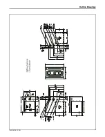
Страница 12: ...12 18 CE01D1 1F EN Outline Drawings...

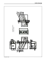
Страница 13: ...18 CE01D1 1F EN 13 O Ou ut tl li in ne e D Dr ra aw wi in ng gs s...

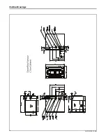
Страница 14: ...14 18 CE01D1 1F EN O Ou ut tl li in ne e D Dr ra aw wi in ng gs s...

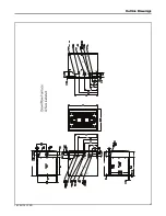
Страница 15: ...18 CE01D1 1F EN 15 O Ou ut tl li in ne e D Dr ra aw wi in ng gs s...

Страница 16: ...16 18 CE01D1 1F EN O Ou ut tl li in ne e D Dr ra aw wi in ng gs s...

Страница 17: ...18 CE01D1 1F EN 17 O Ou ut tl li in ne e D Dr ra aw wi in ng gs s...

Страница 18: ...ace General Installation The following sections give general instructions for the installation of the gas furnaces S Series Furnace Panel Removal Note Use a 5 16 Allen wrench to remove the front panel...

Страница 19: ...the default location The upflow furnace default is left side gas piping The downflow furnace default is right side gas piping Upflow furnace with gas piping on left side Upflow furnace with gas piping...

Страница 20: ...upflow furnace default is left side gas piping The downflow furnace default is right side gas piping Horizontal left furnace with gas piping out left side Horizontal left furnace with gas piping out r...

Страница 21: ...closing its individual manual shut off valve during any pressure testing of the gas supply piping system at test pressures equal to or less than 1 2 psig 3 5 kPa Note Maximum pressure to the gas valve...

Страница 22: ...utility company and compare to the nameplate rating This must not exceed the nameplate rating Gas Flow in Cubic Feet Per Minute 2 Cubic Foot Dial Sec Flow Sec Flow Sec Flow Sec Flow 8 900 29 248 50 14...

Страница 23: ...ameplate rating unless the unit is derated for high altitude d Replace and tighten the regulator cover screw securely 6 Adjust 2nd stage gas heat by removing the high HI adjustment regulator cover scr...

Страница 24: ...ICES DRILL SIZE PART NUMBER DRILL SIZE PART NUMBER 44 ORF00501 54 ORF00555 45 ORF00644 55 ORF00693 46 ORF00909 56 ORF00907 47 ORF00910 57 ORF00908 48 ORF01099 58 ORF01338 49 ORF00503 59 ORF01339 50 OR...

Страница 25: ...em must not be interchanged with other vent systems or unlisted pipe or fittings Plastic components specified primers and glues must be from a single system manufacturer and not intermixed with other...

Страница 26: ...into the furnace compartment which could lead to premature component failure We recommend following one of the options to prevent this condition from occurring and possibly damaging components within...

Страница 27: ...to prevent condensation from occurring in the furnace cabinet Do not tee AC condensate and combustion air condensate trap together Option 3 Side combustion air intake If sloping the combustion air in...

Страница 28: ...e house The inlet air coming from the interior of the house must meet combustion requirements for area etc as shown in the section AIR FOR COMBUSTION AND VENTILATION in this Installer s Guide Furnace...

Страница 29: ...yp pr ro op py yl le en ne e v ve en nt ti in ng g s sy ys st te em ms s F Fo ol ll lo ow w t th he e m ma an nu uf fa ac ct tu ur re er r s s i in ns st ta al ll la at ti io on n i in ns st tr ru uc...

Страница 30: ...20 158 ASTM D1785 D2241 SDR SERIES 158 ASTM D2241 CPVC ASTM STANDARD PIPE TYPE ALLOWABLE TEMPERATURE F MARKING D2846 CPVC 41 212 ASTM D2846 F441 SCH 40 80 212 ASTM F441 F442 SDR SERIES 212 ASTM F442 A...

Страница 31: ...L TABLE EQUIVALENT VENT LENGTHS MAY BE DIFFERENT FROM WHAT IS SHOWN ABOVE REFER TO THE VENTING SYSTEM MANUFACTURER S INSTALLATION INSTRUCTIONS FOR APPROPRIATE VENTING DIAMETERS AND EQUIVALENT LENGTHS...

Страница 32: ...ing coupling it is used for 3 vent pipe installation Make sure the marking TOP is located on the top side of the pipe in horizontal venting applications The straight side of the coupling must be on bo...

Страница 33: ...t metal Minimum dimensions are 12 x12 Shield must be fastened to both inside and outside of wall Use screws or anchor type fasteners suited to the outside or inside wall surfaces NONCOMBUSTIBLE MATERI...

Страница 34: ...ions for two pipe venting system Both terminations must be located in the same pressure zone Important Maintain 12 minimum clearance above highest anticipated snow level or grade whichever is greater...

Страница 35: ...in 3 feet of the vent terminal The vent for this appliance shall not terminate 1 Over public walkways or 2 Near soffit vents or crawl space vents or other areas where condensate or vapor could create...

Страница 36: ...e met at the time of completion of installation the owner shall have a period of thirty 30 days to comply with the above requirements provided however that during said thirty 30 day period a battery o...

Страница 37: ...lding or the combustion air inlet to any other appliance 6 inches 15 cm for appliances 10 000 Btuh 3 kw 12 inches 30 cm for appliances 10 000 Btuh 3 kw and 100 000 Btuh 30 kw 36 inches 91 cm for appli...

Страница 38: ...building or the combustion air inlet to any other appliance 6 inches 15 cm for appliances 10 000 Btuh 3 kw 12 inches 30 cm for appliances 10 000 Btuh 3 kw and 100 000 Btuh 30 kw 36 inches 91 cm for ap...

Страница 39: ...RIBS FROM CAP COMBUSTION AIR ROOF FLASHING BOOT FIELD SUPPLIED COMBUSTION AIR VENT ELBOW FIELD SUPPLIED MAINTAIN 12 IN 18 IN FOR CANADA MINIMUM CLEARANCE ABOVE HIGHEST ANTICIPATED SNOW LEVEL MAXIMUM O...

Страница 40: ...TABLE SUPPORT METHOD Venting Through an UNUSED Chimney Important Refer to Section 12 6 8 of NFPA 54 ANSI 223 1 2012 when routing vent piping through a chimney Important The single wall flue pipe joint...

Отзывы: