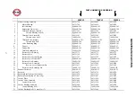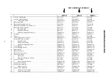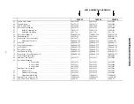
21
MAINTENANCE SECTION
DISASSEMBLY
General Instructions
1.
Do not disassemble the tool any further than neces-
sary to replace or repair damaged parts.
2.
When grasping a tool or part in a vise, always use
leather–covered or copper–covered vise jaws to
protect the surface of the part and help prevent
distortion. This is particularly true of threaded mem-
bers and housings.
3.
Do not remove any part which is a press fit in or on
an assembly unless the removal of that part is
necessary for repairs or replacement.
Disassembly of the Impulse Mechanism
1.
Use a hooked wire to pull the Retaining Pin Spring
(68) out of the end of the Drive Shaft (66) and
remove the Socket Retaining Pin (67).
2.
Using a hex wrench, remove the three Hammer Case
Cap Screws (85) and Lock Washers (86). Lift the
Hammer Case (82) off the Motor Housing (1) over
the Drive Shaft. Remove the Hammer Case Gasket
(80).
3.
Lift the assembled mechanism off the Rotor (42).
4.
Grasp the flats of the Housing (47) in vise jaws with
the output end of the Drive Shaft downward.
5.
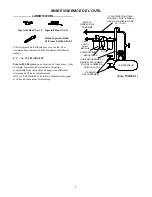
Insert the pins of the Spanner Plug from the
No. 700A–99 Tool Kit into two holes in the Housing
Cap (49). Using a wrench on the plug, unscrew and
remove the Housing Cap from the Housing. (Refer to
Dwg. TPD1267.)
SPANNER PLUG
CLOCKWISE TO LOOSEN
(Dwg. TPD1267)
6.
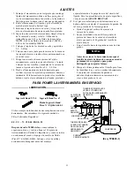
Stand the Disassembly Arbor from the Tool Kit, large
end downward, on a workbench or the table of an
arbor press. Insert the output end of the Drive Shaft
into the central opening and either tap the Housing
downward off the components or use the Pressing
Sleeve in the Kit to press the Housing downward off
the components. (Refer to Dwg. TPD1268.)
PRESSING SLEEVE
TAP EDGE LIGHTLY WITH BRASS
HAMMER OR USE PRESSING
SLEEVE FROM TOOL KIT
DISASSEMBLY ARBOR
FROM TOOL KIT
HOUSING
(Dwg. TPD1268)
In the following step, do not remove or turn the
Shut–off Adjustment Screw (72) located in the
Front Liner Cover (71). It is the Screw with the
paint in the wrench opening.
7.
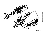
Disassemble the components of the mechanism in the
sequence shown in Drawing TPA1481 on Page 16.
Disassembly of the Motor
1. Grasp the Motor Housing (1) in vise jaws with the
Backcap (23) upward.
2. Using a hex wrench, remove the three Backcap
Screws (36) and Lock Washers (37).
3. Lifting straight upward, remove the Backcap and as-
sembled shut–off mechanism from the Motor Hous-
ing and also the Backcap Gasket (35). Set the as-
sembled Backcap aside.
4. Remove the Housing from the vise jaws and insert a
rod into the central opening in the output end of the
rotor shaft.
5. While holding the motor end of the Housing above a
piece of cardboard on the workbench, lightly tap the
rod to remove the Rear End Plate Assembly (38),
Rotor (42) and Vanes (43).
6. On the table of an arbor press, support the Rear End
Plate with blocks as close to the Rotor as possible and
press the Rotor out of the Rear End Plate and Rear
Rotor Bearing (39).
Содержание 500PS3
Страница 16: ...MAINTENANCE SECTION 16 Dwg TPA1481 ...


