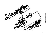
22
MAINTENANCE SECTION
In the following two steps, do not enlarge or
damage the shaft hole in the End Plate.
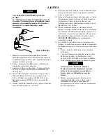
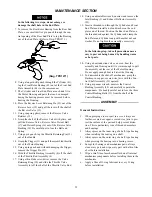
7. To remove the Rear Rotor Bearing from the Rear End
Plate, use a small drift or pin punch through the cen-
tral opening of the Rear End Plate to tap the Bearing
out of the End Plate. (Refer to Dwg. TPD1271.)
(Dwg. TPD1271)
8. Using a longer drift punch through the Cylinder (41),
tap the Front Rotor Bearing (45) out of the Front End
Plate Assembly (44) in the same manner.
9. The Cylinder and Front End Plate are a shrink fit in
the Motor Housing and parts that can be damaged
during the heating process must be removed before
heating the Housing.
10. Press the Reverse Lever Retaining Pin (21) out of the
Reverse Lever (19) and pull the lever off the shaft of
the Reverse Valve (15).
11. Using snap ring pliers, remove the Reverse Valve
Retainer (18).
12. Grasp the shaft of the Reverse Valve with pliers, and
pull the Reverse Valve, Reverse Valve Detent Ball
(17) and Detent Spring (16) out of the Reverse Valve
Bushing (14). Be careful not to lose the Ball and
Spring.
13. Using a pin punch, tap the Throttle Retaining Pin (13)
out of the Handle.
14. Grasp the Trigger (11) and pull the assembled throttle
out of the Motor Housing.
15. Using a pin punch and without damaging the Trigger,
remove the Trigger Pin (12).
16. Slide the Throttle Bushing Assembly (4) off the shaft
of the Throttle Rod Assembly (8).
17. Using a thin blade screwdriver, remove the Valve
Retaining Ring (10) and slide the Throttle Valve
Assembly (6) off the shaft of the Throttle Valve Rod.
18. Using an adjustable wrench, unscrew and remove the
Inlet Bushing (2) and Exhaust Deflector Assembly
(22).
19. Insert a threaded rod through the Cylinder and Front
End Plate and install a nut and washer on the end
plate end of the rod. Position the Rear End Plate on
the threaded rod against the Cylinder and clamp the
End Plates and Cylinder snug with another nut and
washer. Do not tighten the assembly excessively.
In the following step, take all precautions neces-
sary to prevent being burned by handling warm
or hot parts.
20. Using a heat induction coil or an oven, heat the
assembly and Housing until it is warm enough to pull
the assembly out the rear of the Motor Housing.
Do not apply enough heat to distort the Housing.
21. To disassemble the shut–off mechanism, grasp the
Backcap in copper–covered vise jaws with the Con-
trol Shaft Assembly (33) upward.
22. Using a spanner wrench, unscrew the Control
Bushing Assembly (29) and carefully separate the
components. Be doubly careful not to lose the three
Control Bushing Balls (31) from the shaft of the
Control Bushing.
ASSEMBLY
General Instructions
1.
When grasping a tool or part in a vise, always use
leather–covered or copper–covered vise jaws to pro-
tect the surface of the part and help prevent distor-
tion. This is particularly true of threaded members
and housings.
2.
Always press on the inner ring of a ball–type bearing
when installing the bearing on a shaft.
3.
Always press on the outer ring of a ball–type bearing
when pressing the bearing into a bearing recess.
4.
Except for bearings and mechanism parts, always
clean every part and wipe every part with a thin film
of oil before installation.
5.
Wipe a thin film of mechanism fluid on all internal
mechanism components before installing them in the
mechanism.
6.
Apply a film of O–ring lubricant to every O–ring
before installation.
Содержание 500PS3
Страница 16: ...MAINTENANCE SECTION 16 Dwg TPA1481 ...

