2.0 INSTALLATION
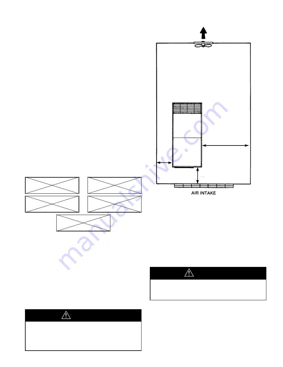
2.1 VENTILATION
Oil flooded rotary air compressors produce large
amounts of heat. Because of this large heat production,
the compressor must be placed in a room with adequate
ventilation.
If heated air from the compressor exhaust is allowed to
recirculate back to the compressor, the compressor will
overheat and shut down. This heat must be exhausted
from the room. You should take this into consideration
when you decide where to place the compressor within
your plant. Consider that the required maintenance
clearance is 3 ft (.9 m) all around the compressor.
However 42” (1.06m), or minimum required by latest NEC
or applicable local codes, must be maintained in front of
control panel.
Ambient temperatures higher than 115°F (46°C)
should be avoided as well as areas of high humidity.
Consider also the environment surrounding or near
the compressor. The area selected for the location of
the compressor should be free of dust, chemicals,
metal filings, paint fumes and overspray.
2.2 FOUNDATION REQUIREMENTS
Refer to the foundation plan for the particular model
compressor to be installed. See Section 8.0.
The compressor can be installed on any level floor that is
capable of supporting it. Compressor weights are listed
on the foundation plans.
When sound transmission is of particular importance it is
often helpful to install a sheet of rubber-fabric-matting, or
cork under the compressor to reduce the possibility of
resonant sounds being transmitted or amplified through
the floor.
2.3 PIPING
The use of plastic bowls on line filters without metal
guards can be hazardous. Their safety can be affected by
either synthetic lubricants or the additives used in mineral
oil. From a safety standpoint, metal bowls should be used
on any pressurized system. Review of your plant air line
system is recommended.
The built-in aftercooler reduces the discharge air
temperature well below the dew point (for most ambient
conditions), therefore, considerable water vapor is
condensed. To remove this condensation, each
compressor with built-in aftercooler is furnished with a
combination condensate separator/trap.
DUST
CHEMICALS
METAL
FILINGS
PAINT
SPRAY
OVERSPRAY
Do not use plastic pipe, soldered copper
fittings or rubber hose for discharge piping.
WARNING
Never elevate the compressor unit
above the floor level. This may allow air
to enter the cabinet under the base.
Performance will be affected.
NOTICE
9
36”
(.9 m)
36” (.9 m)
42” (1.06m) OR
CODE MINIMUM
Содержание 100-200
Страница 17: ...FIGURE 2 5 1 TYPICAL OUTDOOR SHELTERED INSTALLATION 15...
Страница 18: ...16 3 0 INTELLISYS INTELLISYS CONTROLLER INGERSOLLrAND INTELLISYS...
Страница 52: ...50 54418074 REV B 8 0 REFERENCE DRAWINGS 8 1 ELECTRICAL SCHEMATIC STAR DELTA...
Страница 53: ...51...
Страница 54: ...52 54622865 REV B 8 2 FOUNDATION PLAN 125 150 HP 90 110KW AIRCOOLED SINGLE STAGE CONTINUED...
Страница 55: ...53 54622865 REV B 8 2 FOUNDATION PLAN 125 150 HP 90 110 KW AIRCOOLED SINGLE STAGE...
Страница 56: ...8 3 FOUNDATION PLAN 200 HP 132 160 KW AIRCOOLED SINGLE STAGE CONTINUED 54622931 REV B 54...
Страница 57: ...8 3 FOUNDATION PLAN 200 HP 132 160 KW AIRCOOLED SINGLE STAGE 54622931 REV B 55...
Страница 58: ...56 8 4 FOUNDATION PLAN 125 150 HP 90 110 KW WATERCOOLED SINGLE STAGE CONTINUED 39925300 REV C...
Страница 59: ...57 8 4 FOUNDATION PLAN 125 150 HP 90 110 KW WATERCOOLED SINGLE STAGE 39925300 REV C...
Страница 60: ...58 8 5 FOUNDATION PLAN 200 HP 132 160 KW WATERCOOLED SINGLE STAGE CONTINUED 39926191 REV C...
Страница 61: ...59 8 5 FOUNDATION PLAN 200 HP 132 160 KW WATERCOOLED SINGLE STAGE 39926191 REV C...
Страница 62: ...60 8 6 FOUNDATION PLAN AIRCOOLED CONTINUED 100 150 HP 75 110 KW TWO STAGE 54622980 REV B...
Страница 63: ...61 54622980 REV B 8 6 FOUNDATION PLAN AIRCOOLED 100 150 HP 75 110 KW TWO STAGE...
Страница 64: ...62 8 7 FOUNDATION PLAN AIRCOOLED CONTINUED 200 HP 132 160 KW TWO STAGE 54623053 REV B...
Страница 65: ...63 54623053 REV B 8 7 FOUNDATION PLAN AIRCOOLED 200 HP 132 160 KW TWO STAGE...
Страница 66: ...64 8 8 FOUNDATION PLAN WATERCOOLED CONTINUED 100 150 HP 75 110 KW TWO STAGE 39925326 REV C...
Страница 67: ...65 8 8 FOUNDATION PLAN WATERCOOLED 100 150 HP 75 110 KW TWO STAGE 39925326 REV C...
Страница 68: ...66 8 9 FOUNDATION PLAN WATERCOOLED CONTINUED 200 HP 132 160 KW TWO STAGE 39926340 REV C...
Страница 69: ...67 8 9 FOUNDATION PLAN WATERCOOLED 200 HP 132 160 KW TWO STAGE 39926340 REV C...
Страница 70: ...68 8 10 FLOW SCHEMATIC AIRCOOLED SINGLE STAGE 54579081 REV A...
Страница 71: ...69...
Страница 72: ...70 8 11 FLOW SCHEMATIC WATERCOOLED 90 F 32 C SINGLE STAGE 54579503 REV A...
Страница 73: ...71...
Страница 74: ...72 8 12 FLOW SCHEMATIC WATERCOOLED 115 F 46 SINGLE STAGE 54579511 REV A...
Страница 75: ...73...
Страница 76: ...74 8 13 FLOW SCHEMATIC AIR COOLED TWO STAGE 54579644 REV A...
Страница 77: ...75...
Страница 78: ...76 8 14 FLOW SCHEMATIC WATERCOOLED 90 F 32 C TWO STAGE 54579693 REV A...
Страница 79: ...77...
Страница 80: ...78 8 15 FLOW SCHEMATIC WATERCOOLED 115 F 46 C TWO STAGE 54579727 REV A...
Страница 81: ...79...
Страница 82: ...80 8 16 TYPICAL SYSTEM FLOW DIAGRAMS TYPICAL SYSTEM FLOW DIAGRAM...
Страница 83: ...81 8 16 TYPICAL SYSTEM FLOW DIAGRAMS...
Страница 84: ...82 8 16 TYPICAL SYSTEM FLOW DIAGRAMS...
Страница 85: ...83 8 16 TYPICAL SYSTEM FLOW DIAGRAMS...
Страница 86: ...84 8 16 TYPICAL SYSTEM FLOW DIAGRAMS...
Страница 90: ...88 DATE RUN TIME WORK DONE QTY UNIT WORK HOURS MEASURE BY 10 0 MAINTENANCE RECORD...
Страница 91: ...89 DATE RUN TIME WORK DONE QTY UNIT WORK HOURS MEASURE BY MAINTENANCE RECORD...
Страница 92: ...90 DATE RUN TIME WORK DONE QTY UNIT WORK HOURS MEASURE BY MAINTENANCE RECORD...
Страница 93: ...91 DATE RUN TIME WORK DONE QTY UNIT WORK HOURS MEASURE BY MAINTENANCE RECORD...


