Nix Product Manual |
Wiring and Connections
INGENIA | 01/22/2019
78
1st order filter cutting frequency
(-3 dB)
6.6 MHz
Sampling rate (analog)
10 ksps
Maximum readable pulse
frequency (digital)
30 MHz
Input impedance
120 Ω resistive differential
100 pF capacitive
1 kΩ to GND
Resolution
10 bits
Specification
Value
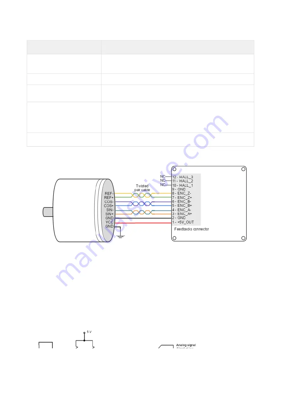
Next figure shows how to connect a Sin-Cos encoder to Nix Servo Drive. Refer to
for more information about connections and wires.
For differential Sin-Cos encoders with peak to peak voltage exceeding 1 Vpp it is recommended to use a series
resistor on ENC_X+ and ENC_X- pins. The value of that resistor should be chosen to attenuate the voltage at the
input around 1 Vpp ± 20%. Use the following formula to determine the resistor that must be placed on each
input. Rin = 50 · ( Vinpp - 1 V). Example: for 3 Vpp Sin-Cos, the resistance in series with each pin should be Rin = 50
· (3 - 1) = 100 Ω.
If no REF (Or Zero index) signal is available leave the ENC_Z- and ENC_Z+ pins floating.
For single ended analog Sin-Cos encoders. Connect the encoder signals to the ENC_x+ (positive) inputs.
• If the average of the sine and cosine is 2.5 V±0.1 V. ENC_x- inputs should be left floating.
• If the average is different to 2.5 V±0.1 V. connect all the ENC_X- inputs to the average value. Some encoders
provide this output and name (confusingly) Vref. The value of the average must be between 0.6 V and 4.4 V.
Circuit model for each differential channel (A, B, REF) is shown in the next figure.


