background image

INFOSEC UPS SYSTEM – 4 rue de la Rigotière – 44700 Orvault – France – www.infosec-ups.com 

Hot Line Tel : +33 (0)2 40 76 15 82 – fax : +33(0)2 40 94 29 51 – [email protected] – 11 11 AA 68 203 16


13


3.3.2.


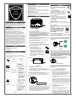
Montage en tour 


3.4.


Présentation des borniers et des connexions de l'onduleur 


3.4.1.


Bornier 


5000 – 6000 – 8000 VA 

10 000 VA

Triphasé 

Monophasé 

Содержание E6 LCD 10K RT

Страница 1: ...Manuel utilisateur User Manual 5 6 8 10 kVA 1 1 10 kVA 3 1...

Страница 2: ...00 Orvault France www infosec ups com Hot Line Tel 33 0 2 40 76 15 82 fax 33 0 2 40 94 29 51 hotline infosec fr 11 11 AA 68 203 16 1 V Ve er rs si io on n F Fr ra an n a ai is se e p p 2 2 E En ng gl...

Страница 3: ...mmunication 10 3 Installation et fonctionnement 11 3 1 D ballage 11 3 2 S lection du lieu d installation 12 3 3 Kit d accessoires d installation 12 3 4 Pr sentation des borniers et des connexions de l...

Страница 4: ...antie ne sera plus valide si le coffret a t ouvert Contacter votre distributeur local S assurer que la tension d alimentation de l onduleur correspond bien celle du secteur Pour emp cher tout chauffem...

Страница 5: ...prot ger vos biens contre une vari t importante d aberrations affectant de nos jours le secteur lectrique Il vous apporte l assurance d une alimentation lectrique fiable propre et stable Il est impor...

Страница 6: ...e 160 secondes dans les 40 ms si la charge est de 105 150 de la puissance nominale et imm diatement lorsqu elle est de 150 L unit revient automatiquement en mode Onduleur lorsque la surcharge dispara...

Страница 7: ...e recommand est de 75 de la capacit nominale lorsque la tension d entr e est de 176 280 VAC et de 50 lorsqu elle est de 160 280 VAC 2 2 Symboles plac s sur le panneau d affichage LCD l ment Symbole De...

Страница 8: ...ortie d onduleur 31 Er14 D faut sur ventilateur 32 Er15 Mauvaise proc dure d entr e en mode Entretien 33 Er16 Erreur de param tres de sortie en syst me parall le 34 Er17 Les chiffres d ID sont en conf...

Страница 9: ...que la valeur de la tension d entr e secteur est dans les limites normales la DEL clignote rapidement pour indiquer que la tension d entr e secteur n est pas dans les limites acceptables La DEL verte...

Страница 10: ...4700 Orvault France www infosec ups com Hot Line Tel 33 0 2 40 76 15 82 fax 33 0 2 40 94 29 51 hotline infosec fr 11 11 AA 68 203 16 9 2 3 2 Description de la face arri re E6 LCD 8000 10000 RT E6 LCD...

Страница 11: ...de surveiller distance l onduleur et ses tats Les cartes optionnelles d interface qui comprennent R2E 2 me RS232 RSE RS485 USE USB DCE Contact sec et la carte SNMP peuvent tre combin es selon les bes...

Страница 12: ...leur Le contenu standard comprend 1 Manuel de d marrage rapide 1 Manuel utilisateur 1 logiciel de communication d onduleur avec c ble RS232 1 Kit d accessoires en m tal L emballage de l onduleur quip...

Страница 13: ...environnement ad quat Suivre les directives suivantes 1 Laisser un d gagement de 30 cm 12 pouces entre la face arri re et le mur 2 Ne pas emp cher la circulation d air au travers des a rateurs lames...

Страница 14: ...e www infosec ups com Hot Line Tel 33 0 2 40 76 15 82 fax 33 0 2 40 94 29 51 hotline infosec fr 11 11 AA 68 203 16 13 3 3 2 Montage en tour 3 4 Pr sentation des borniers et des connexions de l onduleu...

Страница 15: ...d truite Mod le d onduleur ENTR E SORTIE DISJONCTEUR C BLE DISJONCTEUR C BLE E6 LCD RT 5000 2 x 32 A 3 x 6 mm 2 x 25 A 3 x 4 mm E6 LCD RT 6000 2 x 40 A 3 x 6 mm 2 x 32 A 3 x 6 mm E6 LCD RT 8000 2 x 50...

Страница 16: ...plac es dans le corps de l onduleur Pour tous les autres onduleurs de 6 10KVA les batteries sont plac es dans un bloc de batteries externe Voir le manuel utilisateur des blocs de batteries qui donne l...

Страница 17: ...sjoncteurs Secteur onduleur et Entr es by pass et l onduleur va d marrer Les DEL vertes et s allument pour indiquer que les tensions Secteur et Entr es by pass sont normales et l cran LCD avec fonctio...

Страница 18: ...rger compl tement 3 5 2 D marrage en mode Batteries d marrage froid 1 S assurer que l onduleur a d j t install avec au moins 1 ensemble 20 l ments de batteries de 12 V 2 Appuyer sur l interrupteur ON...

Страница 19: ...s de d filement vers le haut ou vers le bas Avec la touche de d filement vers le bas l cran LCD va pr senter la s quence d affichage suivante C Tension entr e Secteur I1 Tension entr e by pass J Fr qu...

Страница 20: ...alarme sonore est activ e On Q2 Il indique que l alarme sonore est d sactiv e Off 2 Appuyer sur la touche pour d filer vers le bas de l cran et v rifier les r glages de l onduleur L cran LCD pr senter...

Страница 21: ...la plage de fr quence est 3 Hz U Il donne la tension de sortie onduleur V1 Il indique que l onduleur fonctionne en Mode normal V2 Il indique que l onduleur fonctionne en Mode ECO V3 Il indique que l o...

Страница 22: ...1 et S2 pr sentent la plage acceptable d entr e by pass qui peut tre 184 Vca 260 Vca ou 195 Vca 260 Vca 5 L affichage T repr sente la plage de fr quence de sortie de l onduleur en by pass les valeurs...

Страница 23: ...pass DEL et LCD Si une anormalit affecte le secteur apr s verrouillage de l onduleur la DEL va s teindre et la DEL va s allumer sur l cran 3 Pour d verrouiller l onduleur proc der comme suit a V rifi...

Страница 24: ...en puis tourner l interrupteur CAM sur le mode By pass dans le coin sup rieur droit de l cran LCD le symbole s affichera Etape 3 Ouvrir Off le disjoncteur de l onduleur et le disjoncteur de l entr e B...

Страница 25: ...ment puis recharger les batteries pendant 8 heures pour voir si l onduleur peut venir en secours normalement sinon contacter imm diatement le distributeur local Er06 Er10 Er12 Er28 et Si le disjoncteu...

Страница 26: ...autonomie est plus courte que pr vu Si l autonomie n est toujours pas satisfaisante apr s 8 heures de charge contacter le distributeur local pour le remplacement des batteries L onduleur se verrouille...

Страница 27: ...ou slot 2 CHB CN5 6 2 Carte RSE RS 485 CN1 est pour la fonction de r sistance de borne Court circuiter les broches 1 2 pour activer la fonction et les broches 2 3 pour la d sactiver CN2 est pour RS48...

Страница 28: ...se en place d un 6 25 Vcc entre les broches 9 et 10 pendant 5 secondes La capacit de chaque contact de relais est 40 Vcc 25 mA Position de mise en place slot1 CHA CN7 ou slot 2 CHB CN8 Sortie de signa...

Страница 29: ...SYSTEM 4 rue de la Rigoti re 44700 Orvault France www infosec ups com Hot Line Tel 33 0 2 40 76 15 82 fax 33 0 2 40 94 29 51 hotline infosec fr 11 11 AA 68 203 16 28 6 6 Mise en place de ces cartes d...

Страница 30: ...eur Mesure LCD Tension fr quence d entr e Tension fr quence de sortie Niveau de charge Tension batterie et temp rature interne Auto diagnostique En mode secteur et via cran LCD par logiciel et autotes...

Страница 31: ...8 3 Installation and Operation 39 3 1 Unpacking 39 3 2 Selecting Installation Position 40 3 3 Installation of Accessories Kit 40 3 4 Terminal Block Explanation UPS connection 41 3 4 Terminal Block Exp...

Страница 32: ...ceable parts inside Your Warranty will be void Contact your local supplier Please make sure that the input voltage of the UPS matches the supply voltage To eliminate any overheating of the UPS keep al...

Страница 33: ...berrations experienced on Utility power lines today It is your insurance for reliable clean and stable voltage supply It is worth taking care to install the system correctly and to have it maintained...

Страница 34: ...uit the UPS holds the system and cuts the output automatically till the short circuit situation is removed manually Should the unit become overheated the internal thermal Switch will detect the heat a...

Страница 35: ...l Description 1 LINE Utility or Bypass Source 2 Battery Low 3 Battery Abnormal 4 UPS Overloading 5 UPS Working in specified mode 6 A Blackout Transfer occurred in UPS Output 7 Bypass Input Abnormal UP...

Страница 36: ...ng Procedure to enter Maintenance Mode 33 Er16 Output Parameters Set Error in Parallel System 34 Er17 ID Numbers are in conflict in Parallel System or ID number Error in single unit 35 Er21 Parallel c...

Страница 37: ...run under redundancy mode Green LED steadily lights up to indicate that the Utility input voltage is within the window the LED flashes flickeringly to indicate that the Utility input voltage is withi...

Страница 38: ...re 44700 Orvault France www infosec ups com Hot Line Tel 33 0 2 40 76 15 82 fax 33 0 2 40 94 29 51 hotline infosec fr 11 11 AA 68 203 16 37 2 3 2 Rear Panel Explanation E6 LCD 8000 10000 RT E6 LCD 600...

Страница 39: ...s With optional interfaces cards which contains R2E 2nd RS232 RSE RS485 USE USB DCE Dry Contact as well as SNMP card you may combine them according to your demand However the R2E card RSE card and USE...

Страница 40: ...ake the UPS out of the PE foam Unwrap the UPS Standard Package includes 1 set of Quick Start Manual 1 set of User s Manual 1 set of UPS communication software with RS232 cable 1 set of Metal Accessori...

Страница 41: ...damage to the UPS and extend the life of the UPS Please follow the advice below 1 Keep at least 30cm 12 inches clearance from the rear panel of the UPS to the wall 2 Do not block the air flow to the...

Страница 42: ...el 33 0 2 40 76 15 82 fax 33 0 2 40 94 29 51 hotline infosec fr 11 11 AA 68 203 16 41 3 3 2 Tower Configuration Setup 3 4 Terminal Block Explanation UPS connection 3 4 1 Terminal block L12 N1 R S T N1...

Страница 43: ...PUT OUTPUT BREAKER CABLE BREAKER CABLE E6 LCD RT 5000 2 x 32 A 3 x 6 mm 2 x 25 A 3 x 4 mm E6 LCD RT 6000 2 x 40 A 3 x 6 mm 2 x 32 A 3 x 6 mm E6 LCD RT 8000 2 x 50 A 3 x 10 mm 2 x 40 A 3 x 6 mm E6 LCD...

Страница 44: ...CD RT 5000 The batteries are fitted inside UPS bank For all other UPS from 6000 to 10kVA the batteries are fitted inside an external battery bank Please refer to the battery bank user s manual for a c...

Страница 45: ...ution panel and the breakers of the UPS Utility and Bypass Inputs and then the UPS starts up Green LEDs light up to show the Utility and Bypass Inputs are normal and the LCD display with parallel func...

Страница 46: ...the batteries of the UPS are fully charged 3 5 2 Start up in Battery Mode Cold Start 1 Make sure the UPS you have has already been installed at least 1 set 20pcs of 12V batteries 2 Push the UPS ON Swi...

Страница 47: ...use scroll up and scroll down key pads When you use scroll down key pad the LCD display will illustrate as Drawing C Voltage from Utility Input Drawing I1 Voltage from Bypass Input Drawing J Frequency...

Страница 48: ...to drawing Q1 Q1 It shows buzzer On Q2 It shows buzzer Off 2 Press key pad to scroll down the screen and check the UPS settings The LCD display will show in consequence between Drawing Q1 buzzer Draw...

Страница 49: ...o wider one T It shows Frequency Window is 3Hz U It shows inverter output voltage V1 It shows the UPS is operated in normal mode V2 It shows the UPS is operated in Eco mode V3 It shows the UPS is oper...

Страница 50: ...an the bypass input acceptable window it can be 184Vac 260Vac or 195Vac 260Vac 5 Drawing T means the bypass frequency window of the Inverter Output the acceptable setting values are 3Hz and 1Hz 6 Draw...

Страница 51: ...e the Utility is abnormal after the UPS is locked the LED will be extinguished and the LCD will be shown on the LCD screen 3 To release the UPS lock please proceed the followings a Check those error m...

Страница 52: ...witch Maintenance Bypass Switch first then turn on the CAM Switch to Bypass mode and at the right hand upper Corner of the LCD screen will show sign Step 3 Turn off the UPS Utility breaker as well as...

Страница 53: ...UPS may backup normally otherwise consult your local distributor right away Er06 Er10 Er12 Er28 If the CB3 is tripped please turn off the UPS completely and keep the CAM switch at position INV before...

Страница 54: ...attery replacement UPS locks itself and it can t be turned off Please refer to chapter 3 5 6 to trouble shoot the problem otherwise consult your local distributor for help 5 Bundled Software Installat...

Страница 55: ...tion Position slot1 CHA CN4 or slot 2 CHB CN5 6 2 RSE RS 485 card CN1 is for the function of the terminal resistor Short pin1 2 to enable the function and short pin2 3 to disable it CN2 for RS485 and...

Страница 56: ...een pin9 and pin10 for 5 seconds The capacity of each relay contact is 40Vdc 25mA Installation Position slot1 CHA CN7 or slot 2 CHB CN8 Flexible signal output for N C Normal close or N O Normal Open c...

Страница 57: ...SYSTEM 4 rue de la Rigoti re 44700 Orvault France www infosec ups com Hot Line Tel 33 0 2 40 76 15 82 fax 33 0 2 40 94 29 51 hotline infosec fr 11 11 AA 68 203 16 56 6 6 The Installation of those Inte...

Страница 58: ...ult Data specified on LCD Input voltage and frequency Output voltage Frequency voltage Charge level Voltage battery internal Temperature Self diagnostics In mains mode from control panel by software a...

Отзывы: