Big Buck Hunter™
Page 12
Version 01/05
© Copyright 2004-2005 Incredible Technologies, Inc. All Rights Reserved. Unauthorized duplication is a violation of applicable law.
All other marks are the properties of their respective owners. All rights reserved.
Wire Harness
1. If you are installing BIG BUCK
HUNTER CALL OF THE WILD
into a cabinet with a pre-installed
JAMMA harness, it may not have
a wire for the test switch. You will
have to add a contact to the edge
connector at the proper position
(position 15). Some cabinets
have only one coin switch input and the coin switches
are wired together. Connect the designated wires to
the coin switches separately.
2. Attach the wire harness connector to the PCB. Be
sure it is mounted correctly.
WARNING!
Make sure you have identified PIN 1 on the connector before
powering up. Plugging the JAMMA connector in backwards will
cause damage to the PCB.
3. It is best to use connectors (not supplied) whenever
joining a set of harness wires to a subassembly. If you
choose to solder wires together, follow this procedure:
4. Strip off about ½" of insulation from the wire.
5. Slide a piece of heat-shrink tubing over the end.
6. Do not leave a lot of excess wire spooled up in your
cabinet. Cut the wires to the length you need plus a
few extra inches. Leave enough for proper cable
dressing. Do not make it stretch across the inside of
the cabinet.
7. Solder the new wire to the original wire. Use a straight
in-line splice.
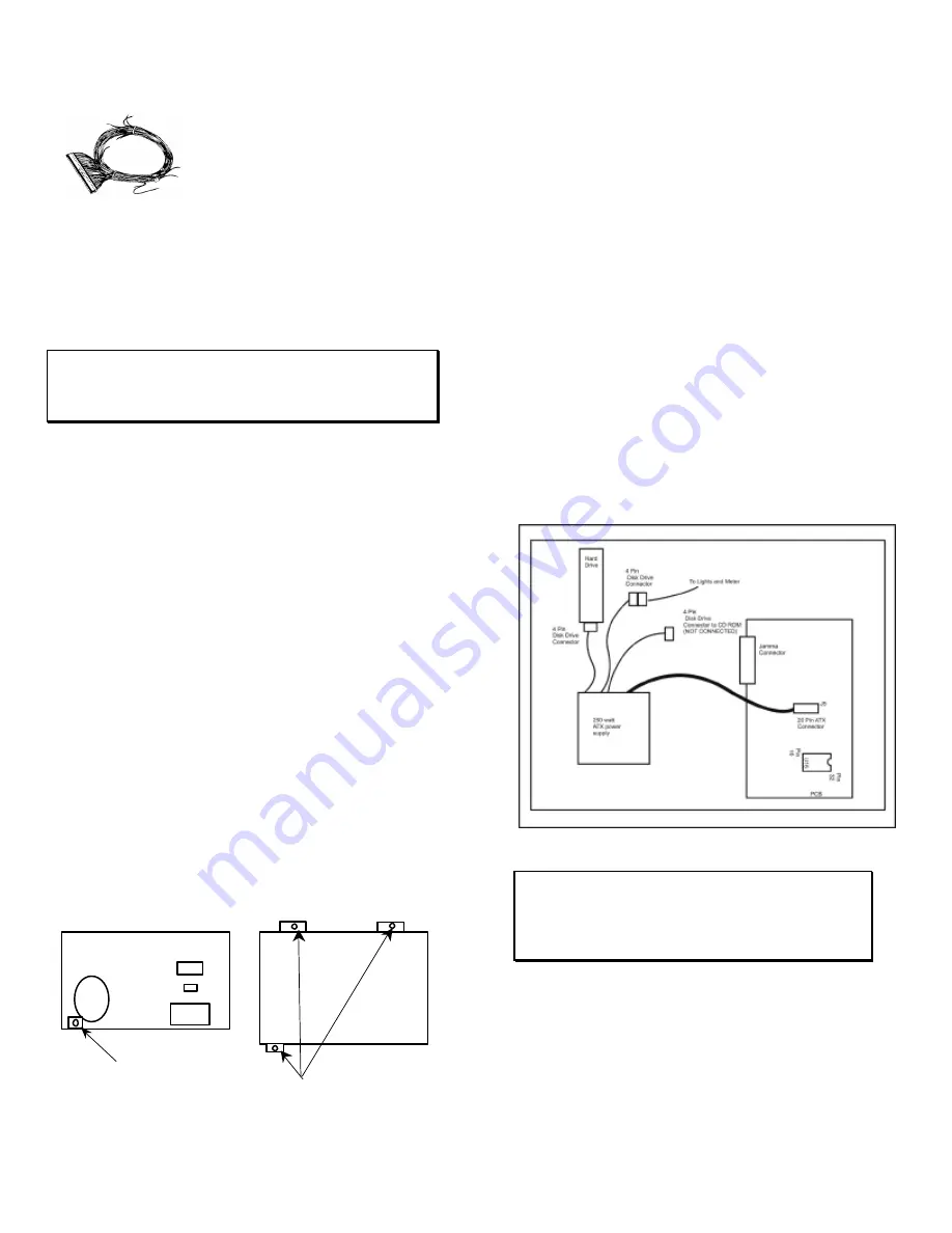
Power Supply and Connections
Because of current consumption, your Big Buck Hunter Call
of the Wild PCB connects directly to a 250-Watt ATX Power
Supply. To correctly mount the ATX Power Supply, you will
need to add a third bracket (supplied):
1. Attach the mounting bracket to the power supply using
the 6-32x1/4” machine screw.
2. Place the power supply in its intended location.
3. Secure the power supply using the three supplied #6x1/2”
hex washer head sheet metal screws.
Instructions for ATX Power Supplies:
1. Turn power to the cabinet and power supply completely
off.
2. Connect the 20-Pin ATX Connector directly into the RED
BOARD socket J5.
3. Locate one Hard Drive Power Connector from the ATX
Power Supply. Use this connector for powering lights,
meters and other non-PCB devices.
4. Locate another Hard Drive power connector on the ATX
Power Supply. Connect this to the Hard Drive.
5. The third Hard Drive connector from the power supply
remains unused. This is meant for future use to perform
updates with a CD ROM drive. Always be sure the CD
ROM drive is set to SLAVE Mode.
6. Turn power on while holding down the start button to
initiate a diagnostic test. Run this test to make sure your
RED BOARD is functioning properly.
7. Be sure to check your JAMMA connector and make sure
it is tightly connected. Detailed instructions and photos
of this installation can be viewed on the Operator
Services section of the IT web site, www.itsgames.com.
WARNING!
ATX Power Supplies require a load to operate. There will be
no Voltage Output if the power supply is not connected to the
main board.
Back View
New Bracket
Top View
3 Mounting Brackets


