


Incite Hochiki-Securiton Interface Module– Rev 1.0
Page 11 of 21
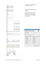
5.4
SYNCRO-SECRDU
5.4.1
I/O Setup and Attributes
The SYNCRO-SECRDU appears to the Syncro panel as a 16 way I/O module.
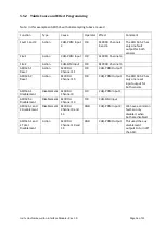
The I/O points are shown in the table below:
I/O
Channel
Function
Syncro Input
or Output
Description
1
General Disablement
Output
NOT USED
2
Access Level 2
Output
Enables SECRDU controls.
3
Fire 1
Output
Fire signal from ASD1
4
Fault 1
Output
Fault signal from ASD1
5
Fire 2
Output
Fire signal from ASD2
6
Fault 2
Output
Fault signal from ASD2
7
Not Used
Output
DO NOT USE
8
Not Used
Output
DO NOT USE
9
Disablement 1.1
Input
Activated whenever the Disablement
function on ASD1 is active. Used to disable
inputs via C&E.
10
Disablement 1.2
Input
May be used as required. Is activated
whenever the Disablement function on
ASD1 is active.
11
Reset 1.1
Input
Activated for 5 seconds whenever the Reset
function on ASD1 is activated. Used to reset
the ASD via C&E.
12
Reset 1.2
Input
May be used as required. Is Activated for 5
seconds whenever the Reset function on
ASD1 is activated.
13
Disablement 2.1
Input
Activated whenever the Disablement
function on ASD2 is active. Used to disable
inputs via C&E.
14
Disablement 2.2
Input
May be used as required. Is activated
whenever the Disablement function on
ASD2 is active.
15
Reset 2.1
Input
Activated for 5 seconds whenever the Reset
function on ASD2 is activated. Used to reset
the ASD via C&E.
16
Reset 2.2
Input
May be used as required. Is Activated for 5
seconds whenever the Reset function on
ASD2 is activated.