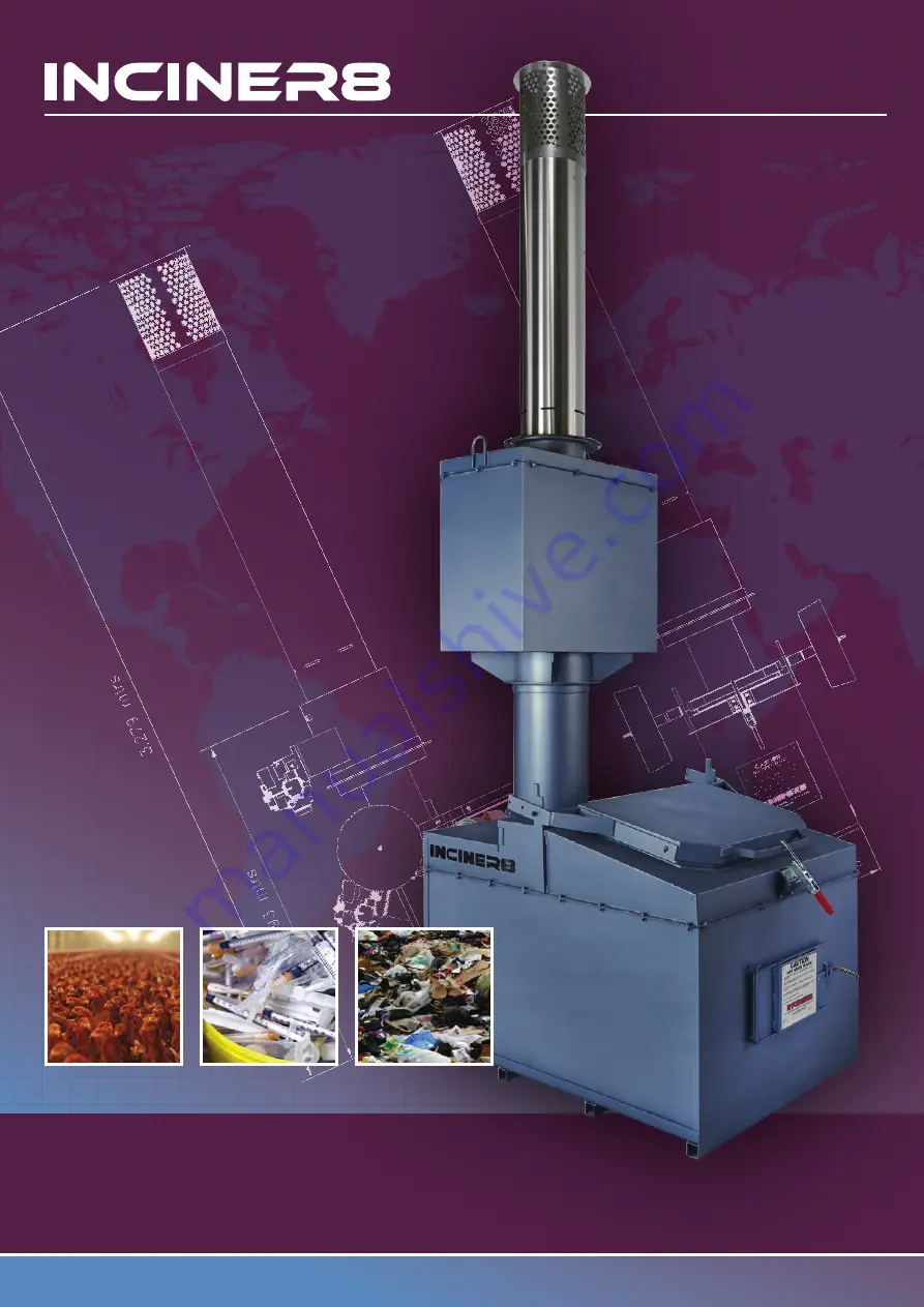
Leading Provider of Thermal Treatment Solutions
+44 (0) 1704 884020
[email protected]
i8-75a Incinerator
Installation & Operation Manual
Страница 1: ...Leading Provider of Thermal Treatment Solutions 44 0 1704 884020 enquiries inciner8 com i8 75a Incinerator Installation Operation Manual ...
Страница 2: ...from existing technology and regulations of safety measures Nevertheless because of improper usage and handling some serious injures for user or other person as well as physical damage to equipment or other goods may occur These incinerators are intended for incineration of waste products and for energy recycling from exhaust heat This is optional equipment Any usage of incinerator beside mentione...
Страница 3: ...ER OR USER ALONE HAS DETERMINED THAT THE PRODUCTS WILL SUITABLY MEET THE REQUIREMENTS OF THEIR INTENDED USE INCINER8 DISCLAIMS ALL OTHER WARRANTIES EXPRESS OR IMPLIED LIMITATIONS OF LIABILITY INCINER8 SHALL NOT BE RESPONSIBLE FOR SPECIAL INDIRECT OR CONSEQUENTIAL DAMAGES LOSS OF PROFITS OR COMMERCIAL LOSS IN ANY WAY CONNECTED WITH THE PRODUCTS WHETHER SUCH CLAIM IS BASED ON CONTRACT WARRANTY NEGLI...
Страница 4: ...n cycle is in process In case of loss of electricity shut down the burner immediately to prevent damage to the burner by heat transferring back for the main chamber Ensure installation and layout is compliant with local building regulations Regularly check the condition of your incinerator to ensure it is in good condition Service every 1 year 1000 hours whichever comes first Do not use cleaning a...
Страница 5: ... 2015 All rights reserved No part of this publication may be reproduced stored in a retrieval system or transmitted in any form or by any means mechanical electronic photocopying recording or otherwise without the prior written permission of INCINER8 No patent liability is assumed with respect to the use of the information contained herein Moreover because INCINER8 is constantly striving to improv...
Страница 6: ...t Please check the package contents against the list above and contact us immediately should anything be missing Main Chamber Secondary Chamber Chimney Stack Cap Control Panel Locking Handle M8 x 20mm hex bolt Control Panel Locking Handles Stack Cap Secondary Chamber Primary Chamber Chimney Fire Rope Mastic Burners M8 x 20mm hex bolt x 8 M10 x 20mm serrated flange bolt x 16 M10 serrated flange nut...
Страница 7: ...ed not to exceed 120 F 50 C or damage may occur to electrical components Local fire and building codes are to be met by the installer If the building has a roof provision will need to be made to allow the chimney to pass through with weather protection as shown on next drawing See APPENDIX 1 for more drawings All the fuel gas or oil supply installations must be done by approved professionals in ac...
Страница 8: ... supplied put a thick beads of the gasket sealant around the refractory lining on the outlet of the secondary chamber d Insert chimney and stack cap on the secondary chamber outlet at securely fasten with 8 M10x20 flanged bolts and nuts e Using the fire cement put a thick bead of sealant around the outlet of the primary chamber f Lift the secondary chamber on the primary chamber ensuring the burne...
Страница 9: ...ndary burner c Remover the mounting plate and gasket from the burner and attach to the studs using the 4 nuts in the burner box d Repeat the above process for the secondary burner e With the burner mount attached the burner can be slotted back on the mount and tighten the retainer nut f Repeat the above process for the secondary burner g On both burner pumps remove the bolt labelled P and insert t...
Страница 10: ...of the chimeny stack a Choose location for control panel and ensure there is enough cable length to reach each burner and the thermocouple can reach the thermocouple port b Attach the cable from the control panel to the burners the primary cable is labelled PRIM and should go to the primary burner and the secondary cable is labelled SEC and will go to the secondary burner Insert and tighten the th...
Страница 11: ...ngle phase 10amp connection required Connection to be made by a qualified electrical engineer Burner connection port Use appropriate burner plugs from the control panel to connect primary and secondary burner Burner plugs are marked as PRIMARY for primary chamber burner and SECONDARY for secondary or afterburner Please remember All our products are designed to operate on 240v mains supply Please e...
Страница 12: ...consult an experienced and qualified gas engineer before attempting any gas installations ONLY A QUALIFIED GAS ENGINEER CAN CARRY OUT THIS STEP DO NOT ATTEMPT THIS IF YOU ARE IN EXPERIENCED Please note You will need to connect these hoses to the fuel supply using 1 4 BSP British Standard Pipe male fittings the supplied hoses have 1 4 BSP female fittings Ensure fuel supply is sufficient to give fue...
Страница 13: ...se consult an experienced and qualified engineer before attempting any fuel installations ONLY A EXPERIENCED ENGINEER CAN CARRY OUT THIS STEP DO NOT ATTEMPT THIS IF YOU ARE IN EXPERIENCED Please note You will need to connect these hoses to the fuel supply using 1 4 BSP British Standard Pipe male fittings the supplied hoses have 1 4 BSP female fittings Ensure fuel supply is sufficient to give fuel ...
Страница 14: ...ctions Connect the 2 Flexible PTFE fuel hoses within the burner box 1 for flow 1 for return Light oil flow return setup Two pipe system example for 2 burners Please note Flow Return example You will need to connect these hoses to the fuel supply using 1 4 BSP British Standard Pipe male fittings the supplied hoses have 1 4 BSP female fittings Ensure fuel supply is sufficient to give fuel pump feedi...
Страница 15: ...nnections Connect the 2 Flexible PTFE fuel hoses within the burner box 1 for flow 1 for return Light oil flow return setup Single pipe system example for 2 burners Please note Flow Return example You will need to connect these hoses to the fuel supply using 1 4 BSP British Standard Pipe male fittings the supplied hoses have 1 4 BSP female fittings Ensure fuel supply is sufficient to give fuel pump...
Страница 16: ...h is completely normal Cracks wider than 2 mm should be treated using High Temp Black Mastic Congratulations your incinerator is now cured Set Temperature 100 C Primary Burner ON 5 Minutes Primary Burner OFF15 Minutes Set Temperature 100 C Primary Burner ON 5 Minutes Primary Burner OFF15 Minutes Set Temperature 200 C Primary Burner ON 15 Minutes Primary Burner OFF15 Minutes Set Temperature 200 C P...
Страница 17: ...temperature or corrosion from waste gases or fluids Water within the refractory concrete Expansion contraction whilst heating cooling Wear tear Too much draw from chimney Too much flammable waste in the main chamber Main chamber overfilled or air setting too high Mastic sealing joint is damaged Thermocouple failure resulting from loose connection Temperature is too low Insufficient oxygen in main ...
Страница 18: ...waste material to flash instantly and too much energy to be released in a very short time Burn procedure Please follow these instructions to define optimal batch size air settings etc Repeat steps 2 6 above gradually increasing batch size in order to define maximum batch size temperature and air settings for a clean combustion for each waste type you are dealing with Most important is to have main...
Страница 19: ...urn or stop Press button 1 Adjust hysteresis value as required Preset value is 25 C To return to home page press button 1 PV Present temperature value from the thermocouple SV set point value for desired burn temperature PV SV 22 800 PV SV HYS 25 0 PV SV WIoN 40 0 PV SV WIoN 40 0 PV SV 1 2 3 4 5 Press button 1 HYS displayed Press button 2 WloN displayed adjust burn time here Using arrow keys 4 5 a...
Страница 20: ...ble damage to the chimney Visible damages to the outside body of the incinerator corrosion of metal parts discolorations leaks Condition of temperature probe Condition of fuel and electrical installation Service procedures every 1 year or 1000 working hours Your unit must be routinely serviced to stay in good working condition Servicing should take place once a year or after 1000 hours usage which...
Страница 21: ...n 855999544 Enter the world of www inciner8 com 44 0 1704 884020 enquiries inciner8 com Leading Provider of Thermal Treatment Solutions Installation Log Must be completed and returned to validate your warranty Incinerator Model Installed by Name Signature Date Company Name Notes Serial Number ...
Страница 22: ...n 855999544 Enter the world of www inciner8 com 44 0 1704 884020 enquiries inciner8 com Leading Provider of Thermal Treatment Solutions Installation Log Must be completed and returned to validate your warranty Incinerator Model Installed by Name Signature Date Company Name Notes Serial Number ...
Страница 23: ...ered in England Wales REG 04866401 VAT Registration 855999544 Enter the world of www inciner8 com 44 0 1704 884020 enquiries inciner8 com Leading Provider of Thermal Treatment Solutions Maintenance Log DATE WORKING HOURS SERVICE ENGINEER NOTES ...
Страница 24: ...Registration 855999544 Enter the world of www inciner8 com 44 0 1704 884020 enquiries inciner8 com Leading Provider of Thermal Treatment Solutions APPENDIX 1 Roof Solution Drawing Most of our models can be covered or containerised A typical roof solution is detailed below Parameter ...
Страница 25: ...ries inciner8 com Leading Provider of Thermal Treatment Solutions CE Certificate Summary I8 1000 model is our largest incinerator This model is a controlled air incinerator providing optimal combustion condi tions for different waste types Top loading design provides liquid retention making this incinerator ideal for incineration of many different waste streams ...