background image

29

the special function keys to change the parameter settings.

The menu shows four parameters. From left to right these are:

Baud rate

—pressing 

F1 

selects between 300, 1200, 2400,

and 9600 baud.

Character length

—pressing 

F2 

selects between 7 and 8 bits

per character.

Parity

—pressing 

F3 

selects between an odd, even, and no

(none) parity bit.

End of line sequence (EOL)

—pressing F4 selects between

a carriage return (CR) only and a carriage return with linefeed
(CR-LF) sequence.

These four parameters must be set to match the settings of the printer
or computer to be connected; refer to the owner’s manual of the
particular device. Settings for interfacing to several In-Situ accesso-
ries are outlined below.

Selecting the Print Width

The HERMIT 2000 supports multiple-column print formats and will
adjust the number of columns of data to match the size of your
printer. The smallest printer size that can be used with the HERMIT
2000 is 24 columns.

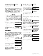
From the I/O setup menu, press 

F3

to select the 

PRNT

 option.

Key in a value for the print width and
press 

ENTER

. The current print width

setting is shown in brackets. You can
select a print width from 24 to 255 columns.

The display will return to the I/O
setup menu.

A print width of 24 columns causes printouts to be made in a format
compatible with older versions of the HERMIT 2000. Print widths of
25 to 255 columns allow the HERMIT 2000 to print in its newer
expanded formats. Settings for interfacing several In-Situ accesso-
ries are outlined below.

Selecting the Plotter Type

Graphics output is supported by most of In-Situ’s field printers and
many compatible printers. The plot size and plot command formats
vary with the type of printer, so you must program the HERMIT 2000
with your printer type.

From the I/O setup menu, press 

F4

to select the 

PLOT

 option.

The current plotter type setting is
shown. Press 

F1

 to cycle through the

available plotter types.

Press 

CLEAR

 or 

ENTER

 when the dis-

play shows the plotter type you want.
The display will then return to the I/
O setup menu.

Note

: Selection of the plotter type doesn’t affect the print width set-

ting or the RS232 parameters. You must set all three menu options
for proper operation of the printer.

Programming a Unit Identification

The HERMIT 2000 has a programmable, eight-character identifica-
tion string that is output with all printouts, plots, and data transfers.
You can use the unit number to identify an instrument, site loca-
tion, etc. The unit number is optional and may be left blank.

From the I/O setup menu, press 

F1

to select the UNIT option.

You will be prompted to enter the unit
number. The current setting of the
unit number is shown in brackets.

Key in the unit number. You can use
the SCAN keys to change a keyed digit
to any character or symbol.

You can key in up to 8 digits, symbols, or characters. Entries of more
than 8 characters will be truncated to the first 8 characters. Entries
less than 8 characters will be left-justified and padded with spaces.
You can enter a blank unit number by keying in a single digit and
scanning it to a space character.

When you press 

ENTER

, the display

will return to the I/O setup menu.

Note

: The unit number is common to all tests. It is not stored indi-

vidually for each test.

I/O setup menu:
UNIT RS232 PRNT PLOT

I/O setup menu:
UNIT RS232 PRNT PLOT

I/O setup menu:
UNIT RS232 PRNT PLOT

Print width  [80]?
 _

Plotter type:
SE1004B

I/O setup menu:
UNIT RS232 PRNT PLOT

I/O setup menu:
UNIT RS232 PRNT PLOT

Unit#   [           ]?
 _

Unit#   [           ]?
 SITE 76_

I/O setup menu:
UNIT RS232 PRNT PLOT

Section 9: Using the RS232 Port

Field Printers

PC’s with

SE1004B

GFP-80

DataTransfer

     Baud rate

1200

9600

9600

     Character length

8

8

8

     Parity

None

None

None

     EOL sequence

CR

CR

CR

                       Field Printers

PC’s with

SE1004B

GFP-80

DataTransfer

    Print width

25

80

24-255

Содержание HERMIT SE2000

Страница 1: ...HERMIT 2000 Environmental Data Logger Model SE2000 Operator s Manual September 1994 Software Version 3 4...

Страница 2: ...its fitness for a particular application In Situ will not be liable for errors contained herein or for incidental or consequential damages in connection with the furnishing perfor mance or use of thi...

Страница 3: ...Defined Sampling 13 The Number of Transducers 14 More About Input Data Types 14 Function Type 15 Level Type 15 Flow Type 15 Dual Type 15 Exiting the Test Setup Menu 15 5 Setting Up Transducers 16 Assi...

Страница 4: ...nsducers 44 Appendix A Accessories 45 Standard Accessories 45 Optional Accessories 45 Appendix B Installation Maintenance Service 46 Unpacking and Inspection 46 Rear Panel 46 Installing Transducers an...

Страница 5: ...revious version of the HERMIT 2000 you may want to take notice of several new features that have been added to software Version 3 4 When you press START to begin a test with Level type inputs the HERM...

Страница 6: ...umption achievingabatterylifemeasuredinyears instead of months Your HERMIT 2000 is naturally narcoleptic fall ing asleep whenever there is no immediate task for the instrument to perform When the inst...

Страница 7: ...nbrackets Ifyouwishtousethe displayed value just press ENTER without typing any digits Theinstrumentwillenterthedefault value and continue to the next dis play In this example the next prompt is for a...

Страница 8: ...ery life by cutting short the normal 60 second sleep delay The READY Display Press and release any key The HER MIT2000willwakeandrespondwith READY TheREADYpromptispresentedwhenevertheHERMIT2000isawake...

Страница 9: ...mayindicateamal function Appendix D contains a list of watchdog error codes The final self test display identifies the HERMIT 2000 s configura tion and all installed options If FAIL is indicated at an...

Страница 10: ...oterasedatauntilthe correct code is entered The indicated tests are then erased and the data storage is set up for our new test The display will show the number of datapointsthatcanbecollectedwith the...

Страница 11: ...again to exit the test setupmenuandreturntotheREADY display From this point on all other functions and menu displays will be automatically tailored to match your SETUP TEST selections For this reason...

Страница 12: ...will leave the transducer disconnected Press CLEAR to return to the trans ducer menu Press CLEAR again to return to the READY display We re now ready to start collecting some data Starting the Test Fr...

Страница 13: ...nput 1 Function 10 03 00 00 00 Input 1 Function 0 0000 2 899 View 50 190114 _ Test 0 Stop Enter to confirm READY Test 0 Stop Battery Life Tip Don t waste battery power and memory endurance by leaving...

Страница 14: ...ument is running a test or if it is waiting for a delayed or alarm start PresstheCLOCKkeywhileattheREADYdisplay The HERMIT 2000 will display the current date and time Press ENTER to begin setting the...

Страница 15: ...ttest number The previous test setup is copied to the new test the available data point capacity and test time in days is displayed followed by the test setup menu Note Thesetupparametersarecopiedfrom...

Страница 16: ...from 1 minute to 1440 minutes one day This mode is useful for collecting long termdataandforrecordingbackgrounddatapriortorunningpump or slug tests Linear mode 2 allows faster sampling 2 to 59 second...

Страница 17: ...ored The data recorded during this period will vary de pending on the coefficient settings but the start of good data should be readily apparent User Defined Sampling The USER sample mode allows you t...

Страница 18: ...ransducers to be used during the test The current selection is shown in brackets WhenyoupressENTER theamount of storage and the maximum test length are displayed and you are returned to the test setup...

Страница 19: ...ate In a manner similar to the level type input the 4 20 mA output of a pressure transducer is converted to PSI PSI is then converted to flow using a standard orifice equation and a programmable calib...

Страница 20: ...umeric keypad or use the SCAN keys to change a keyed digit to any character or sym bol You can key in up to 8 digits sym bols or characters Longer entries will be truncated to the first 8 char acters...

Страница 21: ...et to zero if not specified DELAY Warmup delay For an In Situ transducer set to 50 mSEC unless specified otherwise You will probably have to de terminethisvaluebyexperimentforthird partytransducers Re...

Страница 22: ...ufacturer this value should not be zero for a pressure transducer OFFS Offset Set to zero if not specified DELAY Warmup delay For an In Situ transducer set to 50 mSEC unless specified otherwise You wi...

Страница 23: ...cttheREF optionfrom the transducer menus Key in a value for the reference level and press ENTER The HERMIT 2000 will power up the transducerandtakeacorresponding reference head reading and then return...

Страница 24: ...s Use the more option to access a deeper menu Use CLEAR to back up to the previous menu level Three of the menu param eters are used to convert the 4 20 mA transducer output to a pressure in PSI units...

Страница 25: ...ere Q Volumetric flow rate in GPM K Orifice coefficient from curve A Orifice area in square inches H Transducer head in feet Flow Setup Procedure You can use the following procedure to properly set up...

Страница 26: ...sducer Readingsonadual modetransducer require about five seconds Thetemperatureandprimaryvalues are displayed simultaneously Reminder Due to the time required to read a dual mode trans ducer all dual...

Страница 27: ...F1 to turn the alarm limit ON Press F2 to turn the alarm limit OFF If you turn the limit on the HERMIT 2000 will prompt you for the low limit Key in your value for the low alarm limit and press ENTER...

Страница 28: ...start function is found in the test setup menu Press the SETUP TEST key at the READY display to access the menu Section 6 Setting Up Alarms 12345678 HH LL SETUP TEST Battery Life Tip The HERMIT 2000 c...

Страница 29: ...the IMMEDIATE start option The HERMIT 2000 will start the test and record the first data point The screen display will vary depending on the sample rate pro grammed for the test In addition the availa...

Страница 30: ...rtautomaticallywhen an alarm is detected Stepping the Test The HERMIT 2000 gives you the option to subdivide a test into steps This feature is useful when running constant rate and stepped rate pump t...

Страница 31: ...READY display Note A test cannot be stopped during the first minute of the log sample mode log cycles 1 and 2 In the Linear 2 sample mode there will be no opportunity to confirm or cancel the STOP se...

Страница 32: ...seconds and then return to the data display Changing the View Percentage Youcanmovequicklytoanotherseg ment of data without scanning by changing the view percentage Press CLEAR to exit the view displa...

Страница 33: ...option The current plotter type setting is shown Press F1 to cycle through the available plotter types PressCLEARorENTERwhenthedis play shows the plotter type you want The display will then return to...

Страница 34: ...encounter difficulties while attempting to print data WhileattheREADYdisplay presstheDUMPDATA key to access the dump data menu The dump data menu contains op tions for printing and plotting data Plot...

Страница 35: ...han nel type of data Surface or TOC mode for a level type and the input chan nel I D if one was set 5 Arecordofthetransducer parametersusedtocollect the data 6 The step number of the dataandthestartda...

Страница 36: ...9 4000 28 321 9 6000 28 321 9 8000 28 321 10 0000 28 321 END SE2000 Environmental Logger 01 05 06 18 Unit Test 0 Setups INPUT 1 INPUT 2 INPUT 3 INPUT 4 Type Level F Level F Level F Level F Mode Surfa...

Страница 37: ...f time There are three basic steps required to plot data Select an axes format Scale the axes to fit the data Plot the data The plot functions are accessed by pressing the DUMP DATA key while at the R...

Страница 38: ...de is particularly useful when you need a com plete plot of long term data but still would like to see some detail in short term variations Division Markings Press F3 in the plot format menu to select...

Страница 39: ...t little infor mation can be extracted from the plot Logarithmic X axis Scaling Scaling of a logarithmic x axis in the semi log or log log modes requires the entry of only two parameters The number of...

Страница 40: ...on the range of the y axis endpoints in either the positive or negative direction You can even swap the po larity of the endpoints For example if the data were surface water levels we might prefer tha...

Страница 41: ...ndpoints such that the from value is less that the to value Incorrect settings for logarithmic scaling will cause plotting to stop with only the header information being printed Select the input chann...

Страница 42: ...4 transducers are used TYPE Set input channels 1 through 3 for LEVEL and input channel 4 for FLOW Next enter the parameters for each of the pressure transducers that will be used to measure level 3 U...

Страница 43: ...ta and recording the pump discharge rate After the firsttwominutesofthetesttheHERMIT2000keyboardwillbeavail able for you to use You can VIEW the data to monitor the progress of the test You can print...

Страница 44: ...hannel 1 to LEVEL type and input channel 2 to FUNCTION type With a 16K byte HERMIT 2000 we can record data for 76 days or roughly two and a half months after water is detected in the creek Next enter...

Страница 45: ...urement units Turn the LOW alarm OFF 8 The high and low alarms for the temperature input should be OFF Starting the Test Since we want to record spring runoff data there is no reason to waste power ch...

Страница 46: ...MIT Do not use any other type of cable as this will compromise the integrity of waterproof operation The alarm contacts and their pinouts on the back cable side of the mating connector are shown below...

Страница 47: ...al diagram If pin 3 is la beled as INPUT DATA IN RECEIVED DATA RD RxD or a similar phrase then the device is DTE otherwise it is DCE The pins on the RS232 cable of the HERMIT that must be connected pr...

Страница 48: ...lly many computers do not require an adapter to work Radio Shack s TRS 80 Model 100 is a good example Transducers Transducers other than those provided by In Situ may be adapted for use with the HERMI...

Страница 49: ...arge8 5K11inch high resolutiongraphic data It operates on its own internal rechargeable battery pack Transducers All of In Situ s transducers come to the customer ready to use fully calibrated and com...

Страница 50: ...Appendix A If any accessory items are missing please contact In Situ im mediately Note Note Note Note Note Transducers and other optional acces sories are shipped separately and should also beinspect...

Страница 51: ...he contacts 3 Replacetheprotectivecapon the instrument connector Transducer Installation Transducers can be installed at any of the input channel connectors on the rear panel of the HERMIT 2000 Transd...

Страница 52: ...IT 2000 2 Remove the car s cigarette lighter and install the adapter in the socket Turn the car s ignition switch to ON or ACC if re quired 3 Wake the HERMIT 2000 to con firm that external power is pr...

Страница 53: ...y damaged if used outside its oper ating specifications Temperature Ranges The storage and operating temperatures for the HERMIT 2000 are 40 to 70 C 40 to 158 F Installation in extremely hot and sunny...

Страница 54: ...ny instrument that proves to be defective pro vided it is returned shipping prepaid to In Situ s Product Service facility The customer is responsible for any customs duties in con nection with the ret...

Страница 55: ...Transport Association IATA consider lithium to be a hazardous material Special packaging la beling and documentation are required for shipping the lithium powered HERMIT 2000 Repairs Instruments retur...

Страница 56: ...9 10 127 12 ZERO Division by zero 13 ARG RANGE Argument out of range 14 SQRT Square root of a negative number 15 LOG 0 Logarithm of zero or a negative number 16 NEG X X Negative value raised to a non...

Страница 57: ...ct voltage 30 VDC or 30 VAC max Contact current 1 ampere max RS232C Interface Output voltage swing 4 VDC min 5 VDC typical Input voltage range 15 VDC max 3 VDC min Baud rate Programmable 300 to 9600 b...

Страница 58: ...d contain the following files DT BAT DATATRAN EXE 2 If you are installing DataTransfer to a floppy diskette insert a blank formatted diskette into drive B 3 Set the system prompt to the drive and or d...

Страница 59: ...ame at the Numeric data file name prompt to indicate where the numeric data will be stored If you do not specify a path name the data file will be created in the drive and directory from which you are...

Страница 60: ...ends of the cable are tight Reminder The serial port on your PC is almost certain to be male The 25 pin female port on your PC is for a printer and will not work for downloading Note The last section...

Страница 61: ...y data points are to be skipped An increment of 1 transfers every data point 2 trans fers every other data point 3 every third data point and so on Press ENTER to select the default increment or key i...

Страница 62: ...the trans fer the instrument will abort immediately MESSAGE SOLUTION Break signal detected This Verify that the communication message may also appear at parameters in DataTransfer and the end of data...

Отзывы: