background image

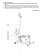
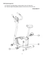
STEP 2 (See Diagram 2) 

A.) 

Note: Extra help may be needed when installing the computer wires in Front Post 
(#12).


B.)  Attach the Front Post (#12) to the Main Frame (#42). Connect the Upper Computer Wire 

(#13) from the bottom of Front Post to the Lower Computer Wire (#14) from the main Fame.  

C.)  Attach the Front Post to Main Frame. Secure them together with four M8 x 5/8” Allen Bolts 

(#16) and four Ø 5/8” Curved Washers (#15). 


DIAGRAM 2 


Содержание BF-6730A

Страница 1: ...rdware Pack Assembly Instruction Parts List Warranty Ordering Parts Model BF 6730A Retain This Manual for Reference 07 06 09 OWNER S MANUAL Deluxe Upright Bike BF 6730A IMPEX INC 14777 DON JULIAN RD C...

Страница 2: ...fore using the machine As a manufacturer we are committed to provide you complete customer satisfaction If you have any questions or find there are missing or damaged parts we guarantee you complete s...

Страница 3: ...using the machine to exercise always do stretching exercises to properly warm up 11 Never operate the machine if the machine is not functioning properly 12 The Maximum Weight Capacity is 300 lbs 13 Re...

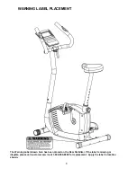
Страница 4: ...PLACEMENT The Warning Label shown here has been placed on the Rear Stabilizer If the label is missing or illegible please call customer service at 1 800 999 8899 for replacement Apply the label in loc...

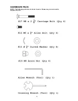
Страница 5: ...HARDWARE PACK NOTE The following parts are not drawn to scale Please use your own ruler to measure the size 4...

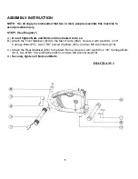
Страница 6: ...ntil instructed to do so B Attach the Front Stabilizer 19 to the Main Frame 42 Secure it with two M8 x 2 3 8 Carriage Bolts 17 two 5 8 Curved Washers 15 and two M8 Acorn Nuts 18 C Attach the Rear Stab...

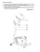
Страница 7: ...12 B Attach the Front Post 12 to the Main Frame 42 Connect the Upper Computer Wire 13 from the bottom of Front Post to the Lower Computer Wire 14 from the main Fame C Attach the Front Post to Main Fr...

Страница 8: ...on Front Post 12 Flip up the handle holder bracket B Attach the Handle 3 to Front Post turn the Handle to desired hand holding position and then flip down the handle holder bracket C Securely thread t...

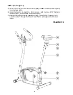
Страница 9: ...the Seat 56 B Attach the Seat to the Seat Post 53 Secure it with the three 5 8 Flat Zinc Washers 55 and three M8 Aircraft Nuts 54 C Insert the Seat Post into the opening on Main Frame 42 Thread the M...

Страница 10: ...STEP 5 See Diagram 5 A Thread the Left Pedal 33L counterclockwise onto the Crank 41 B Thread the Right Pedal 33R clockwise onto the Crank on the other side DIAGRAM 5 9...

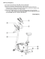
Страница 11: ...9 from the Computer Attach the Computer to the computer base on the Front Post 12 secure the Computer to the Front Post with the four M5 x 3 8 Philips Screws D Plug the AC Adapter 29 to110v outlet an...

Страница 12: ...11...

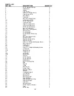
Страница 13: ...4 23 Tension Cable 1 24 Magnetic Sensor Wire 1 25 Magnetic Sensor 1 26 ST4 2 x Philips Self tapping Screw 10 27 M12 Lock Knob 1 28 Power Cord 1 29 AC Adapter 1 30 ST4 2 x 1 Philips Self tapping Screw...

Страница 14: ...t or other damages with respect to any economic loss loss of property loss of revenues or profits loss of enjoyments or use costs of removal installation or other consequential damages or whatsoever n...

Отзывы: