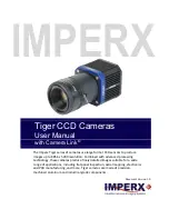
Imperx Tiger T2040 Скачать руководство пользователя страница 1


IMPERX


Tiger CCD Cameras 


User Manual 


with Camera Link

®


The Imperx Tiger series of cameras use large format CCD sensors to produce 
images up to 8856 x 5280 resolution. Combined with advanced processing 
technology, these cameras produce finely detailed images suitable for a wide 
range of applications, including flat panel inspection, aerial mapping, electronics 
and PCB manufacturing, and more. Tiger cameras are made of precision-
machined aluminum and industrial grade components.  


Document Version 1.0 


Содержание Tiger T2040

Страница 1: ...x 5280 resolution Combined with advanced processing technology these cameras produce finely detailed images suitable for a wide range of applications including flat panel inspection aerial mapping ele...

Страница 2: ...Tiger CCD Cameras with Camera Link User Manual November 27 2017 Page 2 of 86 Rev 1 0 REVISION HISTORY Revision Date Reviser Comments 1 0 11 27 2017 R Johnston Initial release...

Страница 3: ...s including flat panel inspection biometrics aerial mapping surveillance traffic management semiconductors and electronics inspection scientific medical Imaging printing homeland security space explor...

Страница 4: ...by IMPERX for its use IMPERX reserves the right to make changes to this information without notice Redistribution of this manual in whole or in part by any means is prohibited without obtaining prior...

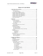
Страница 5: ...D Status 23 2 2 Power Supply 24 2 2 1 Power Supply for Active EF Mounts 25 2 3 Cable Assembly 26 2 4 Mechanical Drawings 26 2 4 1 Large Tiger Cameras 26 2 4 2 Small Tiger Camera 28 2 4 3 Small Tiger C...

Страница 6: ...61 3 9 2 1 Ruggedized Cameras Master AOI Slave AOI 61 3 9 2 2 Industrialized Camera AOI 62 3 9 3 Image Structure 62 3 9 4 Image Corrections 63 3 9 5 Test 64 3 10 Color Panel 65 3 11 Temperature Contr...

Страница 7: ...side load driver 23 Figure 10 PS12V04A power supply ordered separately 24 Figure 11 The PS12V07A power supply 25 Figure 12 PS12V07B power supply showing connection to EF Mount 25 Figure 13 CLM T6640...

Страница 8: ...Slave AOI settings 61 Figure 52 Industrialized camera AOI 62 Figure 53 Image structure settings 62 Figure 54 Image correction settings 63 Figure 55 Image test settings 64 Figure 56 Color screen 65 Fig...

Страница 9: ...h Camera Link User Manual November 27 2017 Page 9 of 86 Rev 1 0 Table 17 Bit depth bit shift output format descriptions 63 Table 18 Image correction descriptions 64 Table 19 Test modes 65 Table 20 Whi...

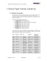
Страница 10: ...egapixel T2040 frame rates up to 34 fps The cameras in this manual are compatible with the Camera Link output interface They include a graphical user interface for camera s configuration software The...

Страница 11: ...to Tiger cameras Some features might apply only to certain cameras or to ruggedized R versions or industrial I versions Camera Link connectivity Ruggedized and industrial versions Lens control for Ca...

Страница 12: ...Interest One Two Master Slave Canon EF Lens Control None Yes Bad Pixel Correction Optional On Off Optional On Off Forced Air Cooling Yes No Camera Output Signal One Two Table 2 Industrial vs Ruggediz...

Страница 13: ...Ruggedized Yes Ruggedized Smear correction Yes Ruggedized Yes Ruggedized Pulse generator Yes Yes Area of interest 1 master 1 slave 1 master 1 slave LUTs 4 User LUTs 4 User LUTs Flat field correction...

Страница 14: ...amic range in 1024 steps 512 to 511 1 step increments Auto gain exposure Yes Ruggedized version Smear correction Yes Ruggedized version Pulse generator Yes Canon EF Lens Control Yes Ruggedized version...

Страница 15: ...25 of Dynamic range in 4096 steps Digital gain 1 0x to 4 0x 0 001x steps 1 0x to 4 0x 0 001x steps Digital offset 12 5 to 12 5 of dynamic range in 1024 steps 512 to 511 1 step increments 12 5 to 12 5...

Страница 16: ...sec nom Analog gain Manual Auto 0 36dB Manual Auto 0 36dB Analog Offset 0 to 25 of Dynamic range in 4096 steps 0 to 25 of Dynamic range in 4096 steps Digital gain 1 0x to 4 0x 0 001x steps 1 0x to 4 0...

Страница 17: ...mera size H x W x L 69 5mm x 69 5mm x 51 4mm Video output 8 bit 10 bit 12 bits Camera interface Camera Link Medium CXP Maximum frame rate 34 fps Long integration Up to 16 seconds Dynamic range 70dB Sh...

Страница 18: ...ng Codes Sample code CLF T8820C RS000 ruggedized CLM T6640M IF000 industrial CLM T6640C RL000 ruggedized and EOS mount lens control Interface Camera Model Sensor Type Ruggedized Industrial Lens Mount...

Страница 19: ...12 pin Hirose male Connector Locking receptacle HR10A 10R 12PB 71 providing power I O interface and Serial RS232 485 interface Figure 3 Camera Link Base Camera output Standard Base Camera Link Mini pr...

Страница 20: ...ply sold separately terminates in a female HIROSE type miniature locking receptacle HR10A 10P 12S 73 and has two small BNC pig tail cables for the external trigger input black and strobe output white...

Страница 21: ...ernal output electrical connections A Input IN 1 Opto Isolated Input signals IN1 and IN1 Rtn are optically isolated and the voltage difference between the two must be positive between 3 3 and 24 volts...

Страница 22: ...ically isolated switch There is no pull up voltage on either contact External pull up voltage of up to 25 volts is required for operation Output is not polarity sensitive AC or DC loads are possible T...

Страница 23: ...back panel of the camera The following LED color and light patterns indicate the camera status and mode of operation LED Condition Status Indication Green steady ON Normal operation You should see a n...

Страница 24: ...d the factory settings If the condition still present contact factory for RMA Red blinks at 2 0 Hz RS232 communication error or Camera Configuration error Re power camera and load factory settings If...

Страница 25: ...r supply adapter is available for the Active EF mount version The adapter brings out the RS 232 communication connection from the camera to the EF mount Figure 12 The operating input voltage ranges fr...

Страница 26: ...ur connections try swapping the cables 2 4 Mechanical Drawings The camera housing is made of high quality 6000 series aluminum construction For maximum flexibility the camera has eight M3X0 5mm mounti...

Страница 27: ...Tiger CCD Cameras with Camera Link User Manual November 27 2017 Page 27 of 86 Rev 1 0 Figure 14 CL large Tiger camera side view Figure 15 CL large Tiger camera front view...

Страница 28: ...of 86 Rev 1 0 Figure 16 CL large Tiger camera back view 2 4 2 Small Tiger Camera The following mechanical drawings show side front and back views of the Camera Link CL small Tiger camera T6640 T6641...

Страница 29: ...CL small Tiger camera front view Figure 19 CL small Tiger camera back view 2 4 3 Small Tiger Camera with Forced Air Cooling The following mechanical drawings show side front and back views of the Came...

Страница 30: ...nual November 27 2017 Page 30 of 86 Rev 1 0 If installing the optional DC fan assembly the height of the small camera increases by 5 8mm from 69 5mm to 75 3mm Figure 20 Small Tiger with fan side view...

Страница 31: ...8810 57mm M 72 Not available T6641 43 3mm F Mount M42 EF Canon Ruggedized model T6640 43 3mm F Mount M42 EF Canon Ruggedized model T4940 32 3mm F Mount M42 EF Canon Ruggedized model T4840 43 3mm F Mou...

Страница 32: ...CCD Cameras with Camera Link User Manual November 27 2017 Page 32 of 86 Rev 1 0 2 6 Spectral Response T6641 Camera Figure 23 T6641 monochrome with micro lens Figure 24 T6641 color Bayer RGB with micro...

Страница 33: ...Tiger CCD Cameras with Camera Link User Manual November 27 2017 Page 33 of 86 Rev 1 0 Figure 25 T6641 color Truesense Sparse CFA with micro lens T6640 Camera Figure 26 T6640 monochrome with micro lens...

Страница 34: ...Tiger CCD Cameras with Camera Link User Manual November 27 2017 Page 34 of 86 Rev 1 0 Figure 27 T6640 color Bayer RGB with micro lens Figure 28 T6640 color Truesense Sparse CFA with micro lens...

Страница 35: ...model 1 Avoid direct exposure to moisture and liquids The camera housing is not hermetically sealed and any exposure to liquids may damage the camera electronics 2 Avoid operating in an environment w...

Страница 36: ...put power 0 75 Max 1 15 W Speed 8500 R P M 10 15 Max air flow at zero static pressure 0 060 Min 0 048 M 3 Min 2 12 Min 1 70 CFM Max air pressure at zero airflow 11 25 Min 7 20 mmH20 0 443 Min 0 283 in...

Страница 37: ...vember 27 2017 Page 37 of 86 Rev 1 0 Dimensions See dimension drawings Weight 11 g Operating temperature 10 to 70 C 40 to 75 C storage Operating humidity 5 to 90 HR 5 to 95 HR storage 2 8 1 DC Fan Dim...

Страница 38: ...correct polarity before connecting the fan to the power source Positive and Negative Damage to the fan may result if connection is with reverse polarity as there is no foolproof method to protect agai...

Страница 39: ...ure 32 T6640 camera with optional fan To replace the fan 1 Remove the four screws M2X10mm holding the existing fan in place 2 Gently pull the fan wires out from between the CL EXT and CL LC boards and...

Страница 40: ...to controller board Note make sure the connector is properly installed and locked 4 Tuck the fan wires between the CL EXT and CL LC boards and position the fan for mounting Figure 35 5 Secure the fan...

Страница 41: ...onfiguration status Dockable menus for Gain AOI Trigger and so on 3 2 Installing the Software Install the Tiger Configurator CamConfig software on the host computer The installer walks you through the...

Страница 42: ...ecutable file Tiger_CL_Z_Y_W_xxxx exe from its location on your computer The Welcome screen appears Click Next to continue 7 On the License screen read the terms and click I Agree to continue 8 On the...

Страница 43: ...ation and then click Install The installer prompts you to uninstall any existing versions of the software from your computer before continuing the installation 10 On the Installation Complete screen s...

Страница 44: ...iger CCD Cameras with Camera Link User Manual November 27 2017 Page 44 of 86 Rev 1 0 11 On the Completing Tiger Camera Link Setup screen click Finish The Tiger Configurator icon appears on your deskto...

Страница 45: ...he Tiger Configurator GUI 1 Locate the Tiger Configurator shortcut icon on your desktop 2 Double click the shortcut 3 The Select Port screen appears Figure 37 Select Port screen To select a camera for...

Страница 46: ...registers are programmable and you can retrieve them by issuing commands At power down the camera clears all registers The factory space is ROM based and write protected It contains the camera s defau...

Страница 47: ...enhancement files loaded by the factory or you can create your own BPM FFC and LUT tables and upload them to the parameter flash memory using the Camera Configurator graphical user interface 3 4 2 Me...

Страница 48: ...current camera settings to the camera User space 2 User 3 saves the current camera settings to the camera User space 3 User 4 saves the current camera settings to the camera User space 4 3 4 2 4 Boot...

Страница 49: ...t field at the bottom of the screen for entering commands Ability to clear the log of all command and data communications A check box to disable polling 3 4 2 6 Download Terminal The Download Terminal...

Страница 50: ...ct Port screen to locate cameras To switch ports 1 Click Menu 2 Select Connection 3 Click Switch Port and select a different port Setting baud rates lets you determine the speed of data transmission A...

Страница 51: ...Controls Not active for Industrial version cameras Image Sets the areas of interest H and V binning modes test pattern generator BPC FFC controls and output data format bit depth and bit shift Color S...

Страница 52: ...nges all analog gain parameters to the same value The Link Offset check box provides the same linking capability for Offset parameters Digital Gain You can set the digital gain from 1 0x to 4 0x in 0...

Страница 53: ...or low The following internal output signals are available for mapping 3 6 1 1 Output Signals for both Industrial and Ruggedized Cameras The following table lists the output signals common to both in...

Страница 54: ...A short pulse 2 s synchronized with the camera frame timing Odd Even Frame Flag A signal based on the camera s internal timing for indicating either odd or even frame It alternates with every frame If...

Страница 55: ...The main resolution is in microseconds and four granularity steps are possible x1 x10 x100 and x 1000 x1000 is equal to 1ms timing resolution Period The amount of time in microseconds determined by th...

Страница 56: ...e triggers select Triggered and use the following options to configure the trigger source and other settings Trigger in Select one of the following active triggering input signals from the drop down l...

Страница 57: ...it arrives while the previous triggering cycle is in process Ignore Camera ignores the next trigger and continues its present operation Accept After Exp The camera uses the next trigger after only aft...

Страница 58: ...is equal to the frame period Pulse Width exposure time is equal to the trigger input pulse width Internal the internal camera timer control exposure based on the Exposure Time setting Exposure Time Al...

Страница 59: ...ect the check boxes for AEC Enable or AGC Enable 2 Select the luminance level the camera is to maintain in the image Options are Average and Peak Average the camera calculates the average value of the...

Страница 60: ...tes larger pixels and less resolution but does not affect the frame rate Select the 2x radio button to combine two adjacent pixels Select the 4x radio button to combine four adjacent pixels No binning...

Страница 61: ...ical sizes 3 Enter horizontal and vertical offset sizes 4 Select Keep Frame Rate to continue the current frame rate The Slave AOI is nested inside the Master AOI You might use the Slave AOI for a regi...

Страница 62: ...ne the boundaries of the AOI Use horizontal and vertical size dimensions to specify the width and height of the AOI in pixels 3 9 3 Image Structure The Tiger camera provides options for adjusting the...

Страница 63: ...corrections using the Threshold slider 0 4095 Off disables Bad Pixel Correction Factory corrects bad pixels identified with predetermined and preloaded defective and hot pixel maps created by the fact...

Страница 64: ...tive complementary colors Table 18 Image correction descriptions 3 9 5 Test Use the test functions on the Image Parameters panel to check camera communications and to generate test images from the Ima...

Страница 65: ...xels and 2 lines thickness indicating the absolute center of the image Table 19 Test modes 3 10 Color Panel White balance lets you adjusts the camera s color setting to preserve the original colors an...

Страница 66: ...t source Select Once to find the correct R G and B coefficients and write down the values Then select Manual and load these coefficients into the camera Leave Manual selected The camera will now apply...

Страница 67: ...or this reason Imperx developed dynamic hot pixel correction The camera performs dynamic hot pixel correction by examining the image output in real time and identifying pixels that are brighter than s...

Страница 68: ...alue It transforms any 12 bit value into any other 12 bit value The camera supports up to four separate lookup tables each consisting of 4096 entries with each entry 12 bits wide The first LUT is pre...

Страница 69: ...internal power protection might engage The protection will disable the power to the CCD display a warning and display a special pattern on the screen We recommend repowering the camera You can rest th...

Страница 70: ...the status LED and verify that it is steady ON Green If it is not refer to the LED section 3 Enable the test mode and verify that the communication between the frame grabber and the camera is establi...

Страница 71: ...extension The lut file has two main sections a header and a table A 1 1 Using an ASCII Text Editor The header section of a file created with an ASCII editor like Microsoft Notepad is a free text area...

Страница 72: ...he camera includes a Defective Pixel Map DPM and Hot Pixel Map HPM You can create your own DPM or HPM file using any standard ASCII text editor or Microsoft Excel Additionally you can use any spreadsh...

Страница 73: ...maximum number of pixels in the DMP list is 128 The maximum number in the HPM list is 1024 The following example shows how to create a simple DPM Locate the defective pixels in the camera and enter t...

Страница 74: ...iption 0x5000 Boot From Register Data 2 0 0x0 Factory 0x1 User 1 0x2 User 2 0x3 User 3 0x4 User 4 0x5 to 0x7 reserved Data 31 3 N A RW Sets default selector determining the configuration space to load...

Страница 75: ...4 Max Exposure Time RO Returns current and maximum camera exposure time in microseconds 0x60A0 Current Gain Luminance Status Data 11 0 Current Analog Gain Ch A Data 23 12 Current Average Luminance Dat...

Страница 76: ...ers T6640 ruggedized version only Address Register Name Data Type Description 0x6200 IRIS Step Value Data 7 0 IRIS Step Data 31 8 N A RW Sets the IRIS step increment value 0x6204 IRIS Close Step WO Cl...

Страница 77: ...ds FOCUS state value 0x6260 CANON Lens Status Data 15 0 Lens Status Data 31 16 N A RO Holds Lens Status value 0x6264 CANON Lens Controller Status Data 15 0 Lens Controller Status Data 31 16 N A RO Hol...

Страница 78: ...31 2 N A RW Sets current binning format in vertical direction 5 vertical binning options 0x0204 Horizontal Binning Mode Data 1 0 0x0 1x horizontal binning 0x1 2x horizontal binning N A 3x 0x3 4x hori...

Страница 79: ...ata 0 0x0 constant frame rate disable 0x1 constant frame rate enable Data 31 1 N A RW Enables camera frame rate to stay the same and independent of AOI vertical window size Exposure Control Registers...

Страница 80: ...desired luminance level Data 31 12 N A RW Sets luminance level to maintain during AEC AGC 0x017C Luminance Type Selection Data 1 0 0x0 average luminance 0x1 peak luminance 0x2 or 0x3 reserved Data 31...

Страница 81: ...Tap Balance 0x0180 Digital Gain Data 9 0 value digital gain Data 31 10 N A RW Sets main digital gain and applies to both channels The step is 0 001x 0x0184 Digital Offset Data 9 0 value digital offset...

Страница 82: ...3 N A Data 31 20 N A RW Selects trigger overlap mode 0x0518 Triggering Mode Selection Data 3 0 0x0 standard triggering 0x1 fast triggering 0x2 double triggering Data 31 4 N A RW Selects triggering mod...

Страница 83: ...generated 0x0540 Pulse Generator Enable Data 0 0x0 disable pulse gen operation 0x1 enable pulse gen operation Data 31 10 N A RW Enables pulse generator Test Pattern Workspace Registers Address Registe...

Страница 84: ...value strobe 1 pulse positions in microseconds Data 31 24 N A RW Sets strobe 1 pulse position with respect to end of frame 0x0564 Strobe 1 Duration Data 23 0 value strobe pulse duration in microsecon...

Страница 85: ...7 bits right Data 31 4 N A RW Selects bit shift steps for camera data output Color Registers Address Register Name Data Type Description 0x0300 Data 0 1 0x0 Off 0x1 WB Once 0x2 WB Auto 0x3 WB Manual 0...

Страница 86: ...2 BPC enable 0x5 Static 2 Dynamic BPC enable Data 31 2 N A RW Enables all Bad Pixels Correction 0x0198 Dynamic Bad Pixel Correction Threshold Level Data 0 11 value Threshold value Data 31 12 N A RW Se...

Отзывы: