
59
1
2
4
3
5
6
10
11
7
9
8
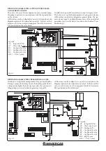
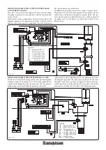
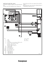
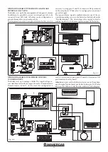
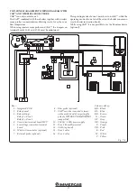
WIRING DIAGRAM WITH HEATING PHASE ACTIVE,
ALARM SIGNAL AND EXTERNAL GAS VALVE.
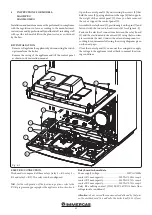
The boiler is set up for the management of any external pump,
the pump is powered in concomitance with the heating request
phase.
All relays can be configured as active heating phase (see the
boiler instruction book), the diagram represents the connection
on relay 1 or 3. If relay 2 is used, pins 57 and 58 of connector
X25 on the relay board must be jumpered.
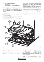
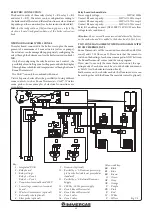
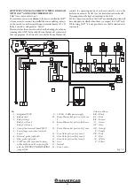
The boiler is set up for the management of any generic alarms.
In addition, it is possible to connect an external gas valve to
be connected to an LPG tank. All relays can be configured
as a generic alarm and as an external gas valve (see the boiler
instruction book)
Fig. 7-6
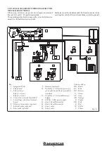
The diagram shows relay 2 as a generic alarm. In this case, it is
necessary to jump pins 57 and 58 of connector X25 positioned
on the relay board. While relay 3 is configured as an external
gas valve supply.
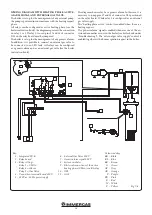
The "heating phase active" control is enabled when there is a
heating request.
The ''generic alarm'' signal is enabled whenever one of the en-
visioned anomalies occurs in the boiler (see boiler book under
''Troubleshooting''). The ''external gas valve supply'' control is
enabled together with a burner ignition request in the boiler.
Key:
1 - Integrated P.C.B.
2 - Relay board
3 - Relay settings:
Relay 1 = CH On
Relay 2 = Alarm
Relay 3 = Gas Valve
4 - Connection terminal board 230 V
5 - 230 Vac - 50 Hz power supply
6 - External Gas Valve 230 V
7 - Generic alarm signal 230 V
8 - System circulator
9 - Electrical connections of the active
heating phase (CH on) via K3 relay
10 - GPL
11 - GAS
Colour code key:
BK - Black
BL - Blue
BR - Brown
G - Green
GY - Grey
OR - Orange
P - Purple
PK - Pink
R - Red
W - White
Y - Yellow


