
57
1
2
3
4
5
6
7
8
10
9
12
11
13
14
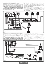
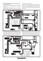
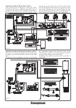
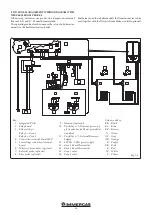
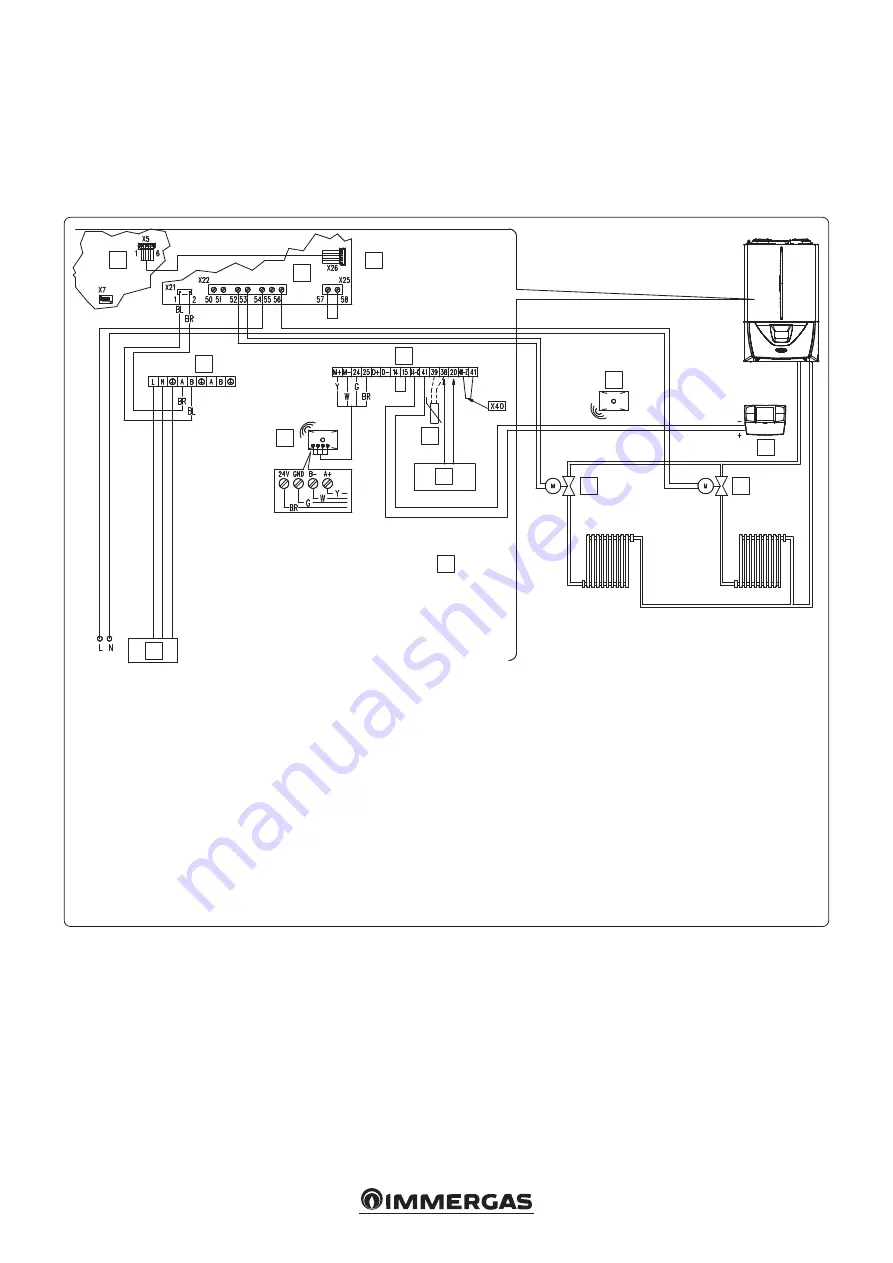
Fig. 7-4
Key:
1 - Integrated P.C.B
2 - Relay board
3 - Relay settings:
Relay 1 = Zone 1
Relay 2 = Zone 2
4 - Connection terminal board 230 V
5 - Low voltage connection terminal
board
6 - Wireless Concentrator (optional)
7 - External probe (optional)
8 - Flow probe (optional)
9 - CAR
V2
must be connected to termi-
nal boards 44 and 41 respecting the
polarity WITHOUT ELIMINATING
jumper X40
10 - 230 Vac - 50 Hz power supply
11 - Zone 2 Room Thermostat
12 - CAR
V2
(optional)
13 - Zone 1 valve
14 - Zone 2 valve
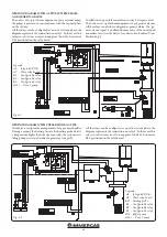
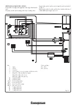
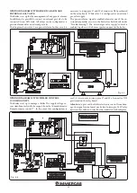
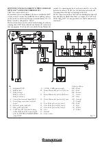
TWO-ZONE MANAGEMENT WIRING DIAGRAM WITH
CAR
V2
AND WIRELESS ROOM PROBE
CAR
V2
can only control zone 1.
The CAR
V2
combined with these boilers together with wireless
room probes can maintain modulating control over the zone
flow temperature.
When using wireless room probes and CAR
V2
, the jumpers on
terminal boards 40-41 and 57-58 must be maintained.
The operating mode of zone 1 must be set on CAR
V2
, while the
operating mode of zone 2 shall be set on the boiler zone menu
(see the boiler instruction book).
While using CAR
V2
it is not possible to use the Dominus device
(optional).
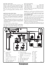
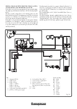
Colour code key:
BK - Black
BL - Blue
BR - Brown
G - Green
GY - Grey
OR - Orange
P - Purple
PK - Pink
R - Red
W - White
Y - Yellow


