


49
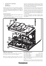
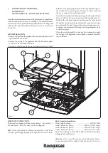
1
3
2
4
5
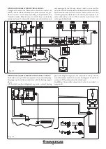
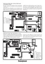
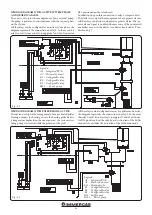
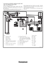
Fig. 5-4
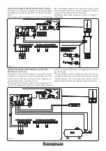
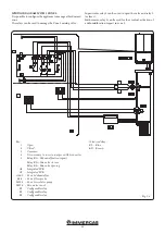
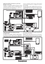
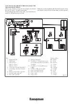
WIRING DIAGRAM WITH 3 ZONES
.
It is possible to configure the appliance to manage a third mixed
zone.
The relays can be used to manage the Zone 3 mixing valve.
In particular, relay 3 can be used to open the valve and relay 2
to close it.
Furthermore, relay 1 can be used for the eventual activation of
a dehumidification request in zone 3.
Key:
1 - Open
2 - Closed
3 - Common
4 - It is necessary to insert a jumper on X25 connector
5 - Relay K1 = Dehumidification request
Relay K2 = Mix valve closure
Relay K3 = Mix valve opening
A3 - Integrated P.C.B.
A7 - Integrated P.C.B.
A16-3 - Zone 3 dehumidifier
B3-3 - Zone 3 flow probe
M10-3 - Zone 3 circulator pump
M31-3 - Mix. valve zone 3
K1 - Configurable relay
K2 - Configurable relay
K3 - Configurable relay
Colour code key:
BL - Blue
BR - Brown


