


50
6
INSTRUCTIONS FOR MODELS:
VICTRIX EXA
Installation and maintenance must be performed in compliance
with the regulations in force, according to the manufacturer's
instructions and by professionally qualified staff, intending staff
with specific technical skills in the plant sector, as envisioned
by the Law.
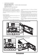
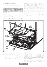
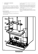
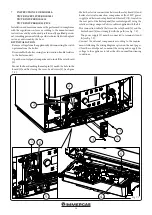
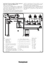
KIT INSTALLATION.
- Remove voltage from the appliance by disconnecting the switch
upstream from the boiler.
- Open the control panel (1) tilting it as prescribed in the boiler
instruction booklet.
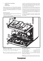
- Open the control panel (1) (see Figure 6-1) unscrewing the
screws (5) and (4).
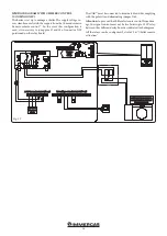
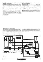
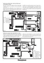
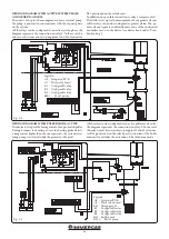
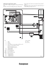
- Perform the electrical connections between the relay board
(6) and the electronic adjustment card (8) using the two wires
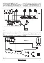
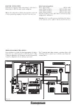
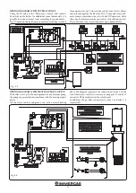
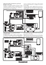
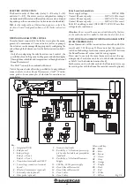
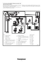
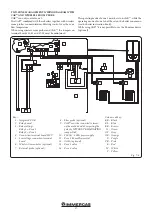
present inside the unit. Connect the external components ac-
cording to requirements following the wiring diagrams given
on the next pages.
- Place the relay board (6) in the dedicated seat (7).
- Close the control panel (1), paying attention not to crush the
cables present. Re-apply voltage to the unit to return to normal
operation.
1
2
3
4
4
5
5
6
7
8
Fig. 6-1


