8
IMER INTERNATIONAL S.p.A.
TR 225 N
Dear Client
&RQJUDWXODWLRQV RQ FKRRVLQJ WKH ,0(5 KRLVW WKH UHOLDEOH DQG
innovative result of years of experience.
WORKING IN SAFETY
To work in complete safety, read the following instructions
carefully before installing the hoist.
This operation and maintenance manual must be kept on site by the
person in charge, e.g. the site foreman, and must always be available
for consultation.
The manual is to be considered an integral part of the machine and
must be kept for future reference (EN 12100-2) until the machine
is disposed of. If it is damaged or lost, a replacement copy may be
requested from the hoist manufacturer.
The manual contains instuctions and warnings relating to the
installation, use and maintenance of the device.
However, the installer and user must be familiar with and experienced
in the use of the machine.
To guarantee complete safety of the operator, operational safety and
long service life, you must comply with the instructions given in this
manual, together with current safety at work regulations (use of boots
and clothing, helmets, safety harnesses, railings around drops, etc.).
DO NOT modify the steel structure or working parts of
the machine in any way.
IMER INTERNATIONAL declines all responsibility for non-compliance
with laws and standards governing the use of lifting equipment,
in particular: unscheduled use, defective power supply, lack of
PDLQWHQDQFHXQDXWKRULVHGPRGL¿FDWLRQVWDPSHULQJZLWKRUGDPDJH
to part or all of the equipment, and partial or total failure to observe
the instructions contained in this manual.
- IMER INTERNATIONAL reserves the right to modify
WKHVSHFL¿FDWLRQVRIWKHPDFKLQHDQGWKHFRQWHQWVRIWKLVPDQXDO
without the obligation to upgrade or update previous models or
editions.
1. GENERAL DESCRIPTION
ATTENTION: Use of lifting equipment requires care
and skill. The machine must be operated by skilled and properly
instructed personnel only.
1) The machine is designed to lift materials only and
for use on building construction sites.
2) Carrying passengers and/or animals is prohibited.
3) The machine must not be used in potentially
explosive atmospheres or underground.
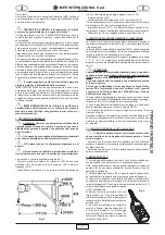
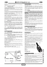
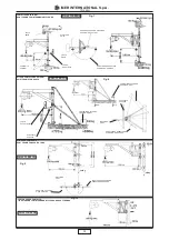
7KHPDFKLQHFRQVLVWVRI¿J
'UXPW\SHZLQFK¿WWHGWRUHGXFWLRQJHDUVKDIWVWHHOURSHOLIW
hook (2) and counterweight (10).
Gearmotor consisting of an electric brake motor (4) and oil bath
reduction gear unit (14).
Electrical system (5).
Up position limit switch lever (9) and down position control lever (17).
Rotary frame (7) with telescopic arm (6), locking handle (8) and frame
locking lever (11).
- Thermal overload (17) which stops the hoist when the current
exceeds the nominal value (press to reset).
Pendant control with 1.5 m cable and three buttons (15).
2. WINCH SUPPORTS
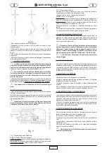
The structure supporting the winch must bear the stress generated
during operation (Fig. 2).
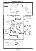
The 400N load is perpendicular to the 7900N load. Since the winch
FDQURWDWHRQLWVSLYRWVWKHVHIRUFHVPXVWEHYHUL¿HGDWDOOSRVLWLRQV
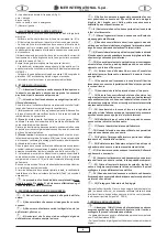
,0(5RIIHUVDZLGHUDQJHRIVXSSRUWVVHH¿JXUHV
for use on building sites, designed to transfer the stresses to the
building structures.
WARNING
The EC Declaration of Conformity enclosed with this manual
is only valid if only IMER components are used for the winch
and support.
If this condition is not complied with, the Declaration loses its
validity and the installation technician must compile a new EC
'HFODUDWLRQRI&RQIRUPLW\DIWHUKDYLQJVDWLV¿HGDOOWKHSURYLVLRQV
of the Machinery Safety Directive 2006/42/EC and its subsequent
PRGL¿FDWLRQVDQGVXSSOHPHQWVUHODWLQJWRWKHDVVHPEO\RIZLQFK
and support.
These forces - referred to support couplings - must be accounted for
in calculations related to supporting structures (scaffolding, balconies,
FHLOLQJVHWFPDGHE\DTXDOL¿HGWHFKQLFLDQ
If the winch is to be secured to scaffolding, it must be adequately
braced (Fig. 13).
To install the various supports, follow the instructions applicable to
each assembly.
When using supports with load bearing capacities other than that of
the hoist, the permissible load bearing capacity of the weakest element
of the system must be prominently displayed.
2.1 INSTALLING THE HOIST ON SITE
$FFHVVWRWKHÀRRUOHYHOIRUORDGLQJPXVWEHSURWHFWHG
by a rail over 1m high and a foot stop.
- Make sure that the lifting run is free from obstacles, and ensure
WKDWQRERG\FDQOHDQRXWLQWRWKHKRLVWZD\IURPLQWHUPHGLDWHÀRRUV
- Cordon off the loading area at ground level to prevent persons
interfering with the work in progress.
3. ASSEMBLY (Fig.1)
1) Only competent, trained personnel may assemble and operate
the hoist.
Given the weight of the hoist, an appropriate number of personnel
must be used for handling and installing it so as to avoid hazardous
situations.
2) The maximum working height (30 m) corresponds to the gearmotor
position i.e. is measured from the top hinge of the support.
3) Secure the support to the building and check the support pins’
vertical alignment (12); then lift the locking lever (11) to insert the
IUDPHEXVKLQJVRQWRWKHSLQVDQG¿WWKHVSOLWSLQUHWDLQHU
4) Fit the telescopic arm (6) to the frame (7) at its minimum extension,
screw the locking handle and washer into
the threaded hole through the slot, and
tighten down (8).
5) When mounting to a trestle support,
¿WWKHWHOHVFRSLFDUPWRWKHFDUULDJH
through the securing holes (Fig. 12) using
bolts and locknuts. For the rest, follow the
instructions for the trestle support
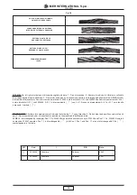
All pendant controls have 3 pushbuttons
(Fig. 3):
black: down
white: up
red: emergency stop.
7) Release the hook.
4. CONNECTION TO THE MAINS
0DNHVXUHWKDWWKHPDLQVYROWDJHLVWKHVDPHDVWKDWVSHFL¿HGRQ
the dataplate.
$OVRFKHFNWKDWWKHPDLQVYROWDJHLVZLWKLQWKHUDQJHWRRI
the nominal value with hoist at maximun load..
7KHSRZHUFDEOHPXVWEH¿WWHGZLWKGLIIHUHQWLDODQGRYHUFXUUHQW
circuit breakers, and the ground cable must have the same cross
section as the cable itself.
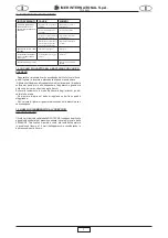
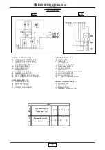
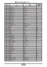
The conductors must be dimensioned in proportion to both the
operating current and their length to avoid voltage drops (Table 1).
Do not use extension leads wound on drums.
- The power cable must be suitable for frequent handling and have
an abrasion-resistant sleeve (for example H07RN-F).
O
R
IG
IN
A
L
I
N
ST
R
U
C
T
IO
N
S
Fig. 3
Fig.2
Содержание TR 225 N
Страница 17: ...TR 225 N 17 IMER INTERNATIONAL S p A...


