I K U S I
5
21/05/2008
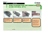
1. Switch off the transmitter.
Remove the two screws
of fixation
of the EP70 EEPROM module
of
the damaged transmitter. In the EP70
EEPROM are stored the system
parameters.
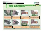
1. Switch off the transmitter.
Remove the two screws
of fixation
of the EP70 EEPROM module
of
the damaged transmitter. In the EP70
EEPROM are stored the system
parameters.
2. Once the two fixation screws are
removed,
extract the EP70
EEPROM module
from the damaged
transmitter.
2. Once the two fixation screws are
removed,
extract the EP70
EEPROM module
from the damaged
transmitter.
3.
Introduce the removed EP70
EEPROM module in the spare
transmitter.
Once placed, to fix it,
tighten the two screws.
3.
Introduce the removed EP70
EEPROM module in the spare
transmitter.
Once placed, to fix it,
tighten the two screws.
4. In order to work with the installed
EP70 EEPROM module,
introducing the battery,
turn on the
key to the ON position and push
and pull the Stop push button
.
The LED will light an instant in
orange-green, it will make some
blinks in green colour during about
15 seconds and it will get
extinguished. Pressing Start push
button the system will start to work
and the LED will get lit in green.
CHART 2
CHART 2
SPARE TRANSMITTER PROGRAMMING
(USING ORIGINAL EP70)
SPARE TRANSMITTER PROGRAMMING
(USING ORIGINAL EP70)
Содержание TM70 Series
Страница 1: ...4 4 2 7 TM70 SERVICE ...


