14
User Actions....Day to Day Operation
1=FLAM
10% LEL
1=FLAM
alarm 1
1=FLAM
FLT UND
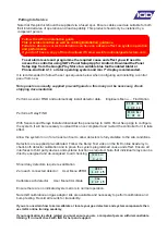
To access the display and switch the backlight on rotate the jog wheel
In Alarm Condition
In Fault Condition
Channel
Number
Channel
Number
Channel
Number
Channel
Gas Type
Channel
Gas Type
Gas or Reading
Type
Current Channel
Reading
The back light turns on making
it easier to see the channel
information. Note that each
channel will be displayed in turn
as indicated by rotating the jog
wheel
The back light will flash red and
the display will indicate which
alarm level and which channel
is in alarm. The sounder will
also activate. Pressing the
button will silence the sounder.
If the gas is still breaching the
alarm threshold it will not be
possible to reset the alarm
Once fully installed the TOC-650 controller will continuously monitor connected gas detectors and
sensors and compare current values with any set alarm thresholds. The display will cycle to display
each channel in turn.
In the event of alarm or fault, CALL FOR SERVICE.
The owner operator is not usually a gas engineer or competent person
as defined by Health and Safety guidelines. If there is any doubt call
your service company and get it checked.
Alarm 1&2
In alarm mode the RED
alarm led will either be
flashing for alarm level 1 or
solid for alarm level 2. The
bottom line of the display will
indicate:
Alarm 1
Alarm 2
In FAULT mode the Yellow fault led
will be on. The bottom line of the
display will indicate as follows:
Alarm Level
FLT UND
FLT OVR
FLT COM
FLT SEN
communication
error to sensors
Sensor Error
Sensor Over Range
Sensor Under Range


